
rain detector
The rain detector circuit is designed to utilize a minimalistic approach while providing essential functionality. The core of the circuit consists of a moisture sensor that detects the presence of water. When water is detected, the sensor triggers a transistor switch that activates a buzzer. The circuit operates on a low voltage of 3 volts, making it suitable for battery operation, which is ideal for portable or outdoor applications.
The buzzer is designed to produce a short, pulsing sound that mimics the sound of dripping water. This is achieved through a simple timing circuit that includes a capacitor and a resistor. The 1 µF capacitor, in conjunction with the resistor, determines the frequency and duration of the buzzer's sound. Adjusting the capacitor value allows for customization of the sound characteristics, making it possible to create a longer or slower beep if desired.
The choice of using silicon transistors in the design ensures that the circuit can operate efficiently at low voltages. The transistors act as switches that control the current flowing to the buzzer, enabling it to produce sound only when rain is detected. The 10 kΩ resistor plays a crucial role in setting the timing for the buzzer. By increasing its value, the duration of the beep can be extended without altering the frequency, although care must be taken to avoid exceeding the operational limits of the transistors.
Overall, this rain detector circuit is a practical solution for alerting users to rain conditions, ensuring that they can take timely action to protect their belongings. Its low power consumption and simple design make it an excellent choice for various applications, from home use to outdoor events.This rain detector will give you a heads-up the instant it starts to rain, hopefully giving you time to close windows and bring in possessions Alternately, a molded power supply with a simple voltage regulator to drop the voltage to 3 volts could be used The battery-powered circuit draws virtually no current when the sensor is dry and the current consumption is low when the buzzer is activated so a couple of AA cells will last a long time When the circuit is triggered, the buzzer is pulsed about once per second for a very short time, giving it a dripping water sound which seems appropriate. A slower, longer beep may be had by increasing the 1 uF capacitor. The circuit is basically a handy flasher circuit that operates well on only 3 volts using ordinary silicon transistors The 10 k resistor may be increased for a longer beep time without decreasing the beep rate but at some point the circuit will cease to function properly, depending on the gain of the transistors.
🔗 External reference
Related Circuits
Detects the presence of a live mains conductor. Minimum parts counting. If the unit is brought close to a live conductor (insulated, and even buried in plaster) capacitive coupling between the live conductor and the probe clocks the counter,...
A circuit designed to extract and measure the modulated carrier of an infrared remote control. This circuit amplifies the entire received signal, allowing the waveform to be displayed on an oscilloscope or a frequency counter. It can measure modulation...
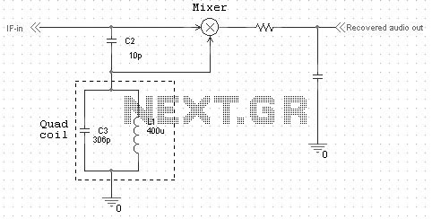
Quadrature FM detectors use a high-reactance capacitor (C2) to produce two signals with a 90 degree phase difference. The phase-shifted signal is then applied to an LC-tuned resonant at the carrier frequency (L1 and C3). Frequency changes will then...
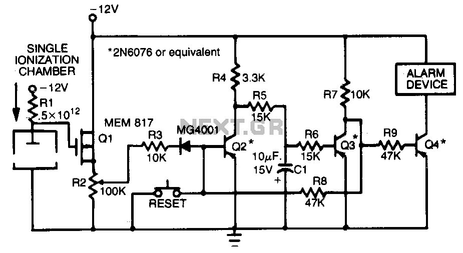
This smoke detector employs a MEM 817 p-channel enhancement mode MOSFET as its buffer amplifier. The sensor operates on the principle that the current decreases when smoke enters the chamber, leading to a negative voltage change at the gate...
This text outlines preliminary plans for a frequency meter designed for a bat detector. The device measures the frequency of the local oscillator in a heterodyne type bat detector, serving as a valuable tool for bat identification. The frequency...
Below is the schematic diagram of an audio input module. This module is capable of producing a DC output voltage that is proportional to the amplitude of the input signal. The audio input module typically consists of several key components...