
Homemade Phone PBX
The talk supply filtering employs a salvaged switching power supply that provides 42VDC for phone talking current. Due to its noisy output, extensive filtering is implemented, utilizing an inductor (essentially half a transformer) and a capacitor to reduce noise. Additional filtering is performed on the main board using RC low pass filters set to 2.34 Hz. An Atmel AVR Atmega328 microcontroller manages tone generation with assistance from a DAC chip. These components generate all busy, dial, and ringing tones by reading WAV files stored in the AVR's flash memory. The AVR also produces DTMF tones for dialing out. It is overclocked to 25MHz to ensure sufficient time for data transfer over a serial shift register interface to the DACs.
An MT8870 DTMF decoder is included for each extension, along with associated circuitry. The DTMF chip connects through a four-bit data bus shared among other DTMF chips, with chip select (CS) lines to identify which chip is being read. The standard (tone detect) pin connects to the Atmega644, allowing it to wait for digits, select the corresponding MT8870, and read a four-bit code representing the dialed digit. A 3.57MHz crystal is located nearby. Isolation transformers couple audio to and from the high voltage phone lines. On the line side, these transformers are AC coupled to the phone line using large capacitors located at the top of the board. Isolation protects the low voltage logic portion of the board from high voltage phone signals. Diode clamping safeguards against significant voltage shifts from actions such as hanging up the phone or pulse dialing.
LM386 amplifiers are positioned above to deliver tones from the DACs to the line through the isolation transformer. The high voltage phone circuitry includes a large black capacitor that is part of the ring trip circuitry, which detects when a phone is picked up during ringing. Another capacitor forms an RC filter to eliminate noise from the phone line and prevent conversations from mixing through the shared power supply. A relay switches between ringing and voice mode, while an optocoupler is in series with the phone to detect its hook state and time pulse dialing.
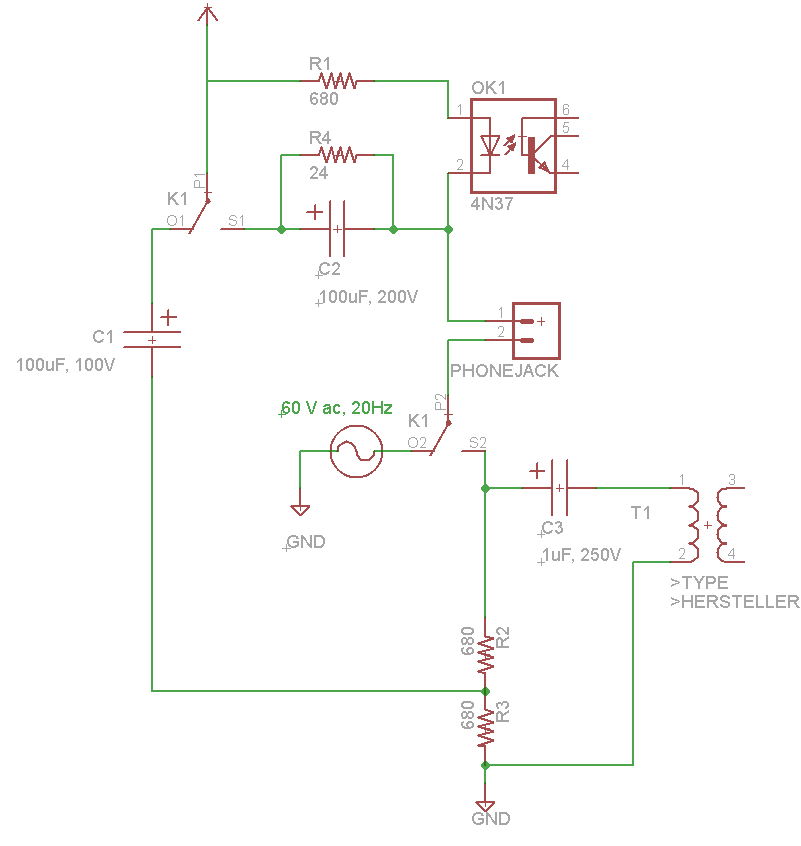
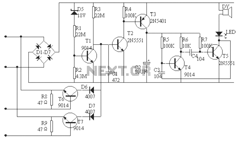
The outside line circuitry allows connection to a real phone company. A relay facilitates line pickup, and a white transformer couples audio between extensions and the outside line. Capacitors AC couple the audio while blocking DC talking current. A ring detection circuit enables the system to detect incoming calls. The board is nearly complete, with dialing (tone and pulse), ringing, call progress tones, and external line calling functioning. Remaining tasks include implementing the 20Hz ringer, a DTMF dialer for the outside line, and operationalizing the crosspoint switch. The circuit interfacing with each telephone extension is shown, with relay K1 switching between idle/talk mode (default) and ring mode. In talk mode, 42VDC flows through resistors R1, R2, and R3 to limit talking current to 20mA. When the telephone is picked up, current flows through Optoisolator 1, signaling the Atmega644 that the telephone is in use. To mitigate PSU noise, C1, R2, and R3 form a low-pass filter to attenuate any noise.Voicemail capacility (although not implemented, there are four ADCs that can be used to sample and record the phone audio) A storage volume (SD card) would need to be connected. This project was inspired by these other homemade exchanges: Markus Wandel and Andrew Holme. My project is not a kit, not from instructions, and not a copy of the above people`s designs. I actually designed and am building all of it from scratch using parts I own and parts I could obtain. Power Supply box: Conatins a 60VDC power supply that will be used to generate high voltage 20Hz AC ringing.
Also contains a 7VAC transformer for 5VDC. Fuses and switches. Talk Supply filtering: A salvages switching power supply provides 42VDC for phone talking current. This supply is noisy so extensive filtering is used. Here, and inductor (really half a transformer) and a capacitor remove some of the noise. The rest is filtered out on the main board using RC low pass filters set to 2. 34 Hz. Atmel AVR Atmega328 microcontroller. This chip handles all tone generation with the help of a DAC chip to the right. These two parts generate all busy, dial, and ringing tones by reading WAV files stored in the flash memeory of the AVR. The AVR also plays DTMF tones to the outside line to dial on it. The AVR is overclocked to 25Mhz so it has enough time to transfer data over a serial shift register interface to the DACs.
MT8870 DTMF decoder. There is one of these and associated circuitry for each extension. The DTMF chip is connected through a four bit data bus shared among the other DTMF chips with CS lines to select what chip is being read. The Std (tone detect) pin is connected to the Atmega644 so it can wait for digits, select the MT8870 where the signal originated, and read off a four bit code refering to the dialed digit.
Nearby is the 3. 57Mhz crystal. Isolation transformers to couple audio to and from the high voltage phone lines. On the line side, these transformers are AC coupled to the phone line using the large capacitors along the very top of the board. Isolation prevents any high voltage phone signals from getting into the low voltage logic portion of the board.
Diode clamping ensures that huge voltage shifts from hanging up the phone or pulse dialing do not make it through the capacitor and transformer. Above are the LM386 amplifiers that deliver tones from the DACs to the line through the isolation transformer.
High voltage phone circuitry. The large black capacitor is part of the ring trip circuitry. (detects when a phone is picked up during ringing) The other capacitor is part of an RC filter that removes noise from the phone line and prevents conversations from mixing through the shared power supply. A relay switches between ringing and voice mode. An optocoupler is in series with the phone to detect its hookstate and to time pulse dialing. Outside Line circuitry. This circuitry allows you to connect an external phone line to a real phone company. A relay allows the system to pick up the line. The white transformer couples audio between the extensions and the outside line. The capacitors AC couple the audio while blocking the DC talking current. A ring detection circuit allows the system to detect incoming calls. Currently, the board is almost complete. Dialing (tone and pulse), ringing, call progress tones, calling through the outside line all work. Still to do is the 20Hz ringer, a DTMF dialer for the outside line, and getting the crosspoint switch to work.
Shown above is the circuit that interfaces to each telephone extension. Relay K1 switches between idle/talk mode (default) and ring mode. In talk mode, 42VDC flows through R1, R2, R3 to limit the talking current to 20mA. When the telephone is picked up, current passes through Optoisolator 1, which signals the Atmega644 that the telephone is now in use. To remove PSU noise, C1, R3, and R2 form a low-pass filter to attentuate any noise. This fil 🔗 External reference
Related Circuits
Tro telephones can be utilized as an intercom through the implementation of this circuit. Traditional rotary phones, particularly those that are non-electronic, may be the most effective for this purpose. Additionally, this method can also power handsets alone. The circuit...
This low-noise microphone amplifier is built with the MAT02 produced by PMI. This microphone amplifier is highly efficient and features a very low noise level. The amplification can be set to either 20 dB or 23.5 dB (10x or...
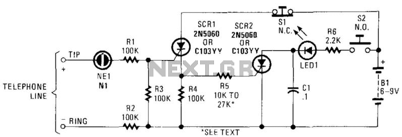
In this circuit, the ringing voltage on a telephone line causes NE-1 to break over, triggering SCR1, which in turn triggers SCR2. If a call has been received, depressing S2 will cause LED1 to light. Depressing S1 resets the...
The phone alarm device is designed to monitor and prevent unauthorized use of a telephone line. When interference signals are detected on the line due to theft attempts, the alarm activates, preventing the thief from making calls while alerting...
An amplifier to drive low to medium impedance headphones built using discrete components. Both halves of the circuit are identical. Both inputs have a DC path to ground via the input 47k control which should be a dual log...
If there is a suspicion that the broadband speed (DSL) is slower than expected, it may be due to incorrect polarity in the phone wall socket. A simple and inexpensive device can be built to determine if the wiring...