
Phone Line Polarity Checker
To construct a device for checking telephone line polarity, a simple circuit can be designed using basic electronic components. The circuit may include a small microcontroller or a simple comparator circuit that can detect the polarity of the DC voltage present on the telephone line. An LED indicator can be employed to visually represent the polarity status: one color for correct polarity and another for incorrect polarity.
The circuit can be powered by the 48V DC bias present on the telephone line, utilizing a voltage divider or a small voltage regulator to step down the voltage to a safe level for the microcontroller. The microcontroller can be programmed to read the voltage levels and determine the polarity by comparing the voltages on the two wires of the telephone line.
In addition, the device can be designed to include a small display or additional LEDs to provide more detailed information, such as the current voltage level and whether the line is operational or not. This added functionality can assist in diagnosing other potential issues with the telephone line that may affect broadband speed.
The construction of this device requires careful attention to the wiring and connections to ensure that it accurately reflects the state of the telephone line. Proper insulation and safety measures should be taken to prevent any electrical hazards, especially when dealing with voltages present in telephone lines.Do you suspect your broadband speed (DSL) is slower than it should be It could be as simple as incorrect polarity in your phone wall socket. Build this very cheap, very simple device to find out whether you need to change your wiring! It might not seem that telephone line polarity is important, since the ring and voice signals sent over telephone
lines are AC. However the lines are actually biased to 48V DC (less when in use) and so the polarity can matter. The main problem with incorrect polarity is that some DSL (Digital Subscriber Line) modems and routers can perform poorly in this circumstance. Since telephone wires are color-coded, it should be possible to simply check that the sockets are wired correctly.
Unfortunately, there are multiple wiring colour schemes and they have changed over time. Believe it or not, the old color scheme (from around 15 years ago) is identical to the current colour scheme except that the polarity of both lines is reversed! This is why so many homes have this problem and yours may well be one of them. The common telephone line is simply a copper pair, ie, two wires. As mentioned, there is usually a 48V DC bias across the pair which drops to around 8V when a telephone is off-hook .
The ring voltage (around 90V AC) and the audio signal voltage (also AC) are overlaid on this DC bias. The DC power is rectified by each telephone on that line to run its own circuitry. Note, though, that this does not include cordless phones which usually use a plugpack, as their power requirements are far in excess of what the telephone line can deliver.
(As an aside, that is the reason it is important to keep a line-powered telephone in your home so you can still make and receive calls if the mains power goes out. Telephone exchanges can usually supply power from their backup batteries for up to some days, even if they are blacked out).
Usually, telephone lines are run with 4-core cable. This allows up to two lines on the one cable. The first line is on the inner pair (pins 2 and 3) and the second line, if present, is on the outer pair (pins 1 and 4). Modern telephones use modular plugs, specifically RJ11 (6P2C, one line), RJ14 (6P4C, one or two lines) or RJ25 (6P6C, 1-3 lines).
By the way, 6P4C stands for six pins, four connectors . Incidentally, RJ12 connectors are physically compatible and commonly available so that is what we have used in this project. Because modern phones rectify the DC voltage from the telephone lines before regulating it and because the ring and voice signals are AC, for voice communications the polarity doesn`t really matter.
🔗 External reference
Related Circuits
A 50-ohm impedance is illustrated in the RF2320 linear amplifier circuit, which is configured for input and output using transmission lines and inductive or capacitive components to create a matching network. The RF2320 linear amplifier circuit is designed to operate...
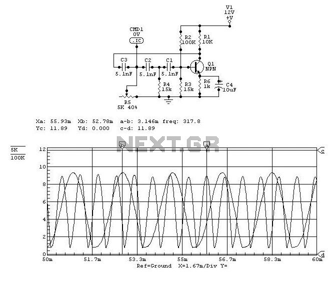
The electronics consist of three op-amp circuits; each built around one half of an NE5532 dual op-amp. Each circuit uses that op-amp in a different configuration. The first circuit is a non-inverting pre-amp, the second is a unity-gain phase-inverter,...
This compact circuit enables automatic recording of phone conversations. It connects to the phone line, the microphone input of a tape recorder, and the remote control jack of the recorder. The circuit detects the voltage on the phone line...
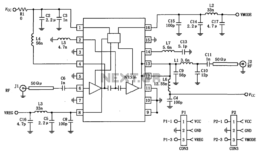
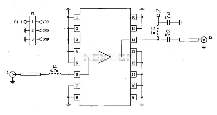
The circuit depicted in the figure is a 380MHz RF2175 linear amplifier application circuit. The radio frequency (RF) signal is input from pin 6 and is processed through a preamplifier, followed by a final power amplifier stage. The output...
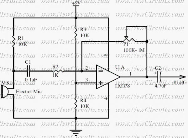
This circuit will be useful if you have an electret microphone that produces a low audio (sound) level and you want to connect it to an amplifier or something like it. The circuit boosts the microphone output voltage to...
Audio can be extracted from a telephone line using a transformer and a capacitor to isolate the line from external equipment. A non-polarized capacitor is placed in series with the transformer line connection to prevent direct current from flowing...