
Telephone Visual Ring Indicator
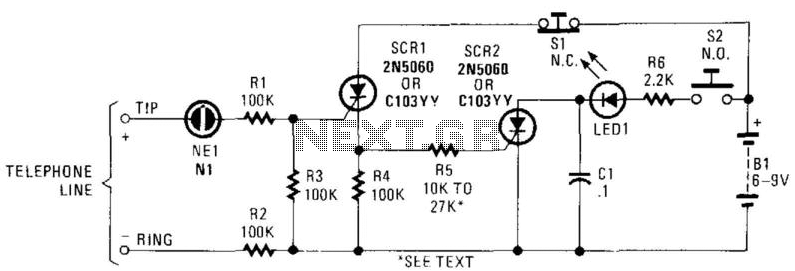
The described circuit utilizes a combination of a neon bulb (NE-1), silicon-controlled rectifiers (SCR1 and SCR2), and a couple of switches (S1 and S2) to efficiently indicate incoming calls with minimal power consumption. The operation begins when the telephone line experiences a ringing voltage, which causes NE-1 to ionize and conduct. This action activates SCR1, allowing current to flow to SCR2, which may be used to drive additional components or indicators.
When a call is received, the user can press switch S2, which activates LED1, providing a visual indication of the incoming call. This design choice ensures that LED1 only illuminates when S2 is pressed, thereby conserving battery power. The circuit is designed to reset when switch S1 is pressed, cutting off the current and returning the system to its idle state. This method of operation not only extends battery life but also enhances the reliability of the circuit by preventing continuous LED illumination, which could otherwise lead to unnecessary power drain.
The overall schematic will typically include the telephone line input, the NE-1 connected in parallel with a resistor to limit current, SCR1 and SCR2 configured in a manner that allows for the triggering mechanism, and the switches S1 and S2 arranged to facilitate user interaction with the circuit. The design emphasizes simplicity and efficiency, making it suitable for applications where power conservation is critical. In this circuit, the ringing voltage on a telephone line causes NE-1 to break over, triggering SCR1, which in turn triggers SCR2. If a call has been received, depressing S2 will cause LED1 to light. Depressing SI resets the circuit. This circuit has the advantage of lower battery drain because LED1 is not left on continuously after a ring signal, but only when S2 is depressed. 🔗 External reference
Related Circuits
Toyota MR2 Exterior Lights Wiring Diagram Manual PDF Download. The Toyota MR2 Exterior Lights Wiring Diagram Manual provides a comprehensive guide for understanding the wiring configurations associated with the exterior lighting system of the Toyota MR2 model. This manual is...
A timing and counting circuit utilizing integrated circuit chips with seven-segment LED displays is employed to show the current lap time, previous lap time, and total number of laps completed on a 1/64th-scale slot car racetrack. A switch activated...
DMRC's uniqueness lies in how it has managed soft issues related to the general public affected by it. To alleviate traffic congestion and chaos around construction sites on main roads, DMRC deployed special personnel to assist Delhi Police. Cars...

This circuit effectively simulates various types of flames, such as a house fire, a campfire, or welding light. This circuit utilizes a combination of light-emitting diodes (LEDs) and a microcontroller to create realistic flame effects. The design typically includes multiple...
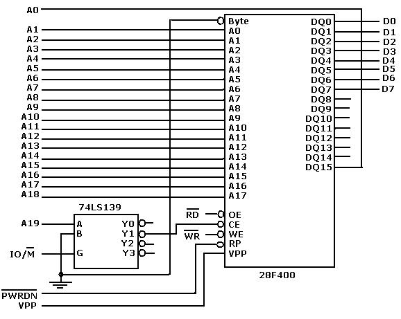
Flash memory, also known as flash RAM, is a type of non-volatile semiconductor memory device that retains stored data even when not powered. It is an enhanced version of electrically erasable programmable read-only memory (EEPROM). The primary distinction between...
A long time ago, when telephones were simple and reliable from an electrical standpoint, telecom operators installed surge protection on all telephone lines exposed to storm risks. Paradoxically, with the advent of delicate and expensive equipment such as electronic...