
Homemade subwoofer playback system 01
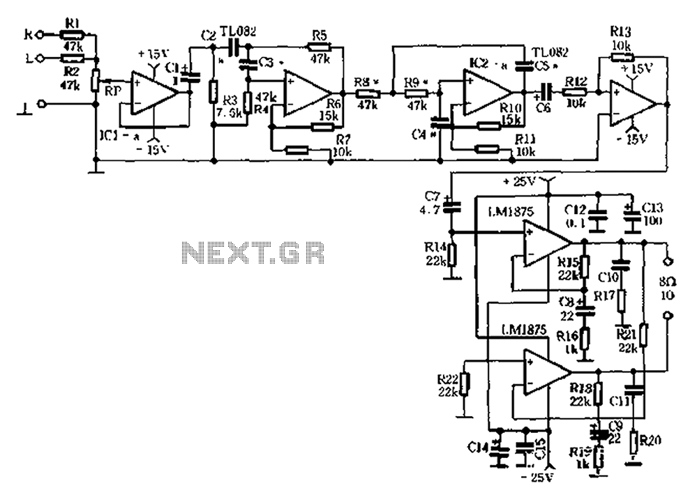
The audio equipment circuit described features a robust configuration for managing low-frequency signals, ensuring efficient reproduction of bass sounds. The left and right channel signals are initially processed through a buffer stage, which isolates the input from the output and prevents loading effects that could degrade audio quality. The JFET input stage operational amplifier (TJ.D82) is critical in providing low noise and high input impedance, which is essential for maintaining the integrity of the audio signal.
Following the buffer stage, the signal is subjected to both high-pass and low-pass filtering. The low-pass filter, with a cutoff frequency set at 20Hz, is designed to allow only the desired low-frequency signals to pass through while attenuating higher frequencies. This is particularly important in subwoofer applications where the focus is on deep bass reproduction. The band crossover filter characteristic enables the system to effectively manage the frequency range from 20Hz to 150Hz, optimizing performance for subwoofers.
The integrated amplifier (LM1875) is notable for its built-in protection features, including overheating and overload safeguards. This ensures that the amplifier operates reliably under various conditions, providing consistent performance without the risk of damage. The output power, while described as low, is sufficient for driving a subwoofer, particularly when combined with the adjustable volume control.
The design considerations for the enclosure are also critical. A closed box configuration is employed, which is known for its ability to produce tight and accurate bass response. The dimensions of the enclosure (510mm x 420mm x 260mm) are carefully chosen to complement the 10-inch, 70W speaker with an 8-ohm impedance. The inclusion of sound-absorbing material within the enclosure enhances acoustic performance by reducing internal reflections and standing waves, further improving sound quality.
In summary, the circuit design effectively manages low-frequency audio signals through a combination of buffering, filtering, and amplification, while the enclosure design maximizes the performance of the speaker, ensuring high-quality bass reproduction suitable for various applications. Audio equipment from the former speaker output terminals left and right channel signal, the Rl, RZ mixed units, after ICla buffer into the high and low pass filter. Filter uses JFET input stage low-noise high-impedance op amp TJ.D82 mouth lC lb, etc. form a low-pass filter with a cutoff frequency of 20Hz o so that the output of the buffer IC2b obtained Figure 9-23 as band crossing pass filter characteristic frequency range of 20Hz ~ 150Hz female power amplifier having overheating, overload protection integrated amplifier LM1875 two form BTI. Amplifier output power nearly loow, capable enough power subwoofer amplifier o RP for the subwoofer volume adjustment.
This special zoom 20Hz ~ 15 0Hz PA ultra-low frequency signal, with any connection type subwoofer. It is generally believed that the inverter box closed box than the lower limit of the bass reproduction, but in actual production t inverted relative to the Q value box speaker has very strict requirements; calculation, production, commissioning slightly wrong, it would lower frequency reproduction not up to the requirements. Without the necessary acoustical testing methods Amateur conditions, the advantages of the phase inverted box actually elusive 6 Relatively speaking, closed box strict requirements for Q value, which is calculated, affecting production, commissioning error on performance than down with smaller boxes, and transient response should be better than inverter box.
The disadvantage of the closed box manifested primarily in their frequency response from a higher frequency began to decline, but this shortcoming just 9-23 available in high and low-pass filter to compensate for only reproducing 20Hz ~}} 5 0Hz signal, you can replay the sealed tank reaches or exceeds the lower limit of inverter box level. Where the election by 10 inches, 70W-made speakers, the impedance of 8n, force closed box size 510mm 420mm 260mm, sound-absorbing material infill.
Related Circuits
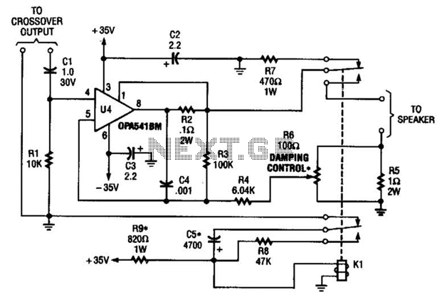
Designed to power a low-frequency subwoofer speaker system, the amplifier can deliver up to 100 W into an 8-ohm load. The OPA541BM operational amplifier, produced by Burr-Brown Corporation, necessitates heatsinking for optimal performance. Additionally, the design incorporates a damping...
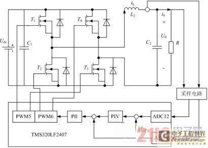
Traditional UPS systems use analog circuit control, which presents significant limitations for both manufacturers and users, regardless of whether they employ technology or SPWM technology. With advancements in information technology, the introduction of high-speed digital signal processing chips, known...
The intersection of industry and data collection systems includes hydrometeorological control systems, robot control systems, and digital image transmission systems. This is facilitated by the electron transport of data information. The data transmission system is a crucial component of...
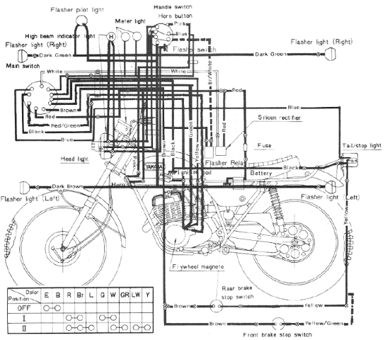
The following image illustrates the Yamaha 175 Wiring Diagram (CT2 and CT3 model) and Electrical System Schematic. It provides detailed information regarding the interconnection and wiring between electrical components of the motorcycle, including the battery, ground, headlight, taillight, horn,...
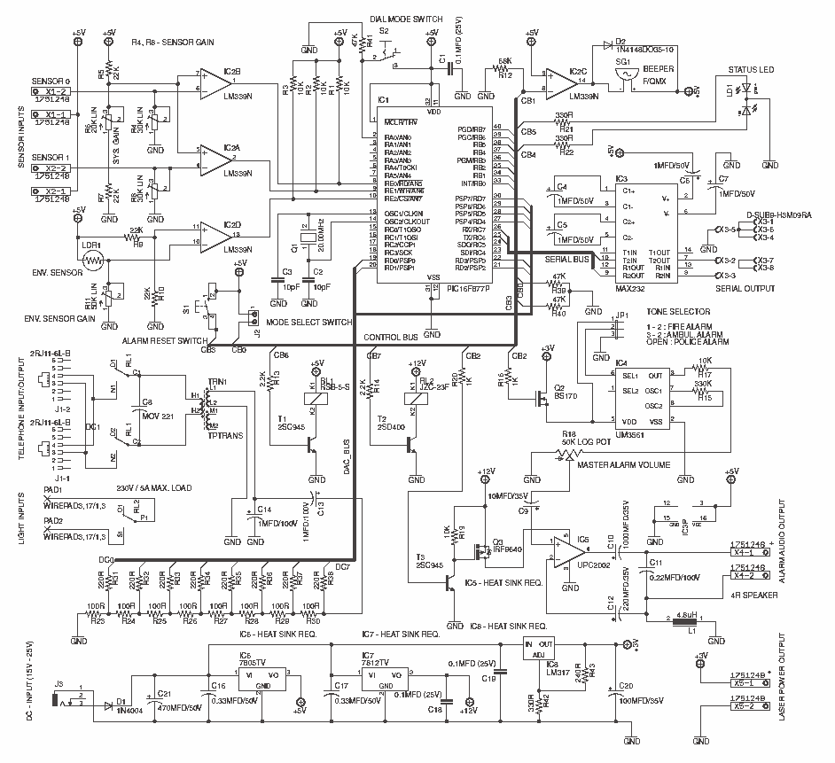
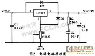
This system uses a Microchip's PIC16F877A as a main controller, LM339 as sensor interface, UM3561 as a tone generator and PC2002 as a speaker driver (audio amplifier). LM7805, LM7812 and LM317 voltage regulators are used to obtain +5V, +12V...
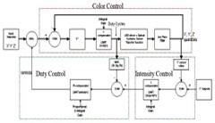
The system utilizes RGB LED light sources, an optical sensor, and a feedback controller. The purpose of employing optical feedback is to ensure color stability over temperature variations, maintain constant brightness, and control any specific color point or brightness...
Warning: include(partials/cookie-banner.php): Failed to open stream: Permission denied in /var/www/html/nextgr/view-circuit.php on line 713
Warning: include(): Failed opening 'partials/cookie-banner.php' for inclusion (include_path='.:/usr/share/php') in /var/www/html/nextgr/view-circuit.php on line 713