
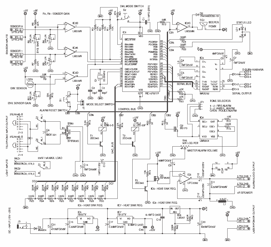
Security Alarm System (PIC16F877A)
Calibration and Testing
Once everything is assembled take following steps to calibrate the system, 1. Remove IC1, IC2, IC3 and IC4 from the IC bases. 2. Apply 18V (to 22V Max.) DC source to the power connector (J3). 3. Check the voltage between Pin12 (GND) and Pin3 of IC2. It need to be 4.8V - 5.1V DC. 4. Check the voltage between GND and E$4 jumper. It need to be 11.7V - 12.3V DC. 5. Check the voltage between Pin1 and Pin3 (GND) of JP1. It need to be 2.5V - 3.1 V 6. If all the above Step 3, 4 and 5 are correct, disconnect the power supply and insert IC1, IC2, IC3 and IC4 in to the appropriate IC bases. Attach suitable speaker to the X4 and connect RS232 cable to the system. 7. Close the jumper J2 (Program Mode) and power on the system. 8. Download and install PuTTY on to the target computer and setup the "Serial" connection with 9600 baud rate. This system also contain 5W (with 4? speaker) audio alarm with three selectable tone configurations, which include Police siren, Fire engine siren and Ambulance siren.
This electronic circuit is designed as a programmable home security system that integrates various components to provide alarm functionality and remote communication capabilities. The central controller, a Microchip PIC16F877A, manages the system's operations, including sensor input processing and alarm activation. The LM339 comparator serves as the sensor interface, enabling the system to interpret signals from light-dependent resistors (LDRs) that detect changes in ambient light levels.
The UM3561 tone generator produces distinct alarm sounds, selectable via a jumper configuration, allowing the user to choose between a police siren, fire engine siren, or ambulance siren. The audio output is amplified by the PC2002 audio amplifier, capable of driving speakers with impedances of 4Ω or 8Ω, delivering a maximum output of 5W.
Power regulation is achieved through three voltage regulators: LM7805 provides +5V, LM7812 supplies +12V, and LM317 is used for +3V, ensuring stable operation of all components. The system is designed to be powered by an external DC supply ranging from 18V to 25V, with a maximum current rating of 2A.
For user interaction and programming, an RS232 interface is employed, allowing configuration of alarm parameters and system settings. The system features a built-in DTMF generator for dialing user-specified phone numbers in response to triggered sensors. The implementation of a status indicator provides visual feedback for operational modes, including run, program, and sensor-triggered states.
Additional features include an alarm volume control, a reset switch for system reinitialization, and connectors for external devices such as lights and lasers. The calibration procedure involves verifying voltage levels across specific pins and jumpers to ensure proper functionality before final assembly and testing.
Overall, this system exemplifies a versatile and cost-effective solution for home security, combining advanced features with user-friendly programming and control mechanisms.This system uses a Microchip's PIC16F877A as a main controller, LM339 as sensor interface, UM3561 as a tone generator and ?PC2002 as a speaker driver (audio amplifier). LM7805, LM7812 and LM317 voltage regulators are used to obtain +5V, +12V and +3V respectively. Touch tone phone dialing interface. 5W High powerful audio alarm. 2 sensor interface with separate sensitivity adjustments. Programmed through the RS232 interface. Build-In intelligent light ON/OFF switch. In this project we design low cost high performance programmable home security system using few LDR's as an input sensors. When above sensor(s) get triggered system may dial the user specified phone number (using build-in DTMF generator) and activate the high power audio alarm and lights.
All the parameters of DTMF generator, audio alarm and light interface are programmed through the RS232 serial interface. Current firmware of this system presents interactive control system through the RS232 interface. This control system consist with the menu driven configuration options, self tests, system report generators, etc.
DC Power input : Attach DC power supply with 18V - 25V (2A Max.) output. RS232 Connector : Connect RS232 serial cable to the port to configure the system. Do not use RS232 Null Modem cable with this port. PHONE/LINE connector : Attach standard RJ12/RJ11 telephone cable connector to this port. One port is need to use with the phone line and remaining port is for the phone (and it is optional). 3V LASER supply : 3V supply line for LASER diode assembly. Connectors for Sensor 1/2 : Attach high sensitive LDRs for these ports. To get the maximum sensitivity it is recommended to use EG&G VACTEC LDRs. Status Indicator : Indicate run, program and sensor trigger modes. Reset Switch : Press this button to reset entire alarm system. This button enable only when the audible alarm get activated. It is not possible to use this function at the phone dialing/ringer states. Phone dialer enable switch : Turn on this switch to enable the phone dialing feature of this system. Environment Sensor : In-circuit LDR to detect light conditions of the environment. Alarm Volume Control : Use this to control the output power (volume) of the audible alarm. 230V Light connector : Attach 230V AC light (or related peripheral) to these terminals. Tone Selector : Configure the master alarm tone from this jumper as follows, 1-2 : Fire Engine Siren 2-3 : Ambulance Siren Open : Police Siren (Do not connect jumper terminal 1-3, this combination may permanently damage the entire system) Beeper : Produce beeps (e.g: at the input error, etc.) Program / Run Switch connector : Attach switch to this header to select Program or Run mode.
Alarm Audio Output : Attach 8? (8W) or 4? (10W) speaker to this connector. Calibration and Testing Once everything is assembled take following steps to calibrate the system, 1. Remove IC1, IC2, IC3 and IC4 from the IC bases. 2. Apply 18V ( to 22V Max.) DC source to the power connector (J3). 3. Check the voltage between Pin12 (GND) and Pin3 of IC2. It need to be 4.8V - 5.1V DC. 4. Check the voltage between GND and E$4 jumper. It need to be 11.7V - 12.3V DC. 5. Check the voltage between Pin1 and Pin3 (GND) of JP1. It need to be 2.5V - 3.1 V 6. If all the above Step 3, 4 and 5 are correct, disconnect the power supply and insert IC1, IC2, IC3 and IC4 in to the appropriate IC bases.
Attach suitable speaker to the X4 and connect RS232 cable to the system. 7. Close the jumper J2 (Program Mode) and power on the system. 8. Download and install PuTTY on to the target computer and setup the "Serial" connection with 9600 baud rate. This system also contain 5W (with 4? speaker) audio alarm with three selectable tone configurations, which include Police siren, Fire engine siren and Ambulance siren.
🔗 External reference
Related Circuits
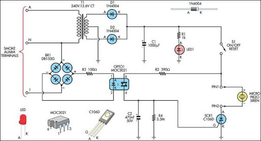
This alarm circuit was designed to monitor a mains-powered smoke detector located in a shed used for dog kennels. It provides complete isolation from the mains, allowing low-voltage (12V) cabling to be run to the alarm circuit located inside...
As an essential component of an advanced computer science course focused on microcomputer systems, it was determined that students would benefit from the design of a single-board computer system utilizing a widely available microprocessor. This decision led to the...
This article discusses a home security alarm circuit designed to detect LPG gas leakage. The circuit utilizes a gas sensor module, SEN 1327, which incorporates a QM 6 gas sensor. The output signal from this gas sensor module is...
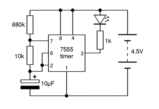
The 7555 timer IC used is a low power version of the standard 555 timer. A super bright red LED is utilized because it provides a bright flash with low current. The 7555 timer IC is a versatile low-power component...
The circuit consists of an ultrasonic transmitter and a receiver that operate at the same frequency. Ultrasonic piezoelectric transducers serve as the output and input devices, respectively, with their frequency of operation determined by the specific devices used. The...

At high speeds, visually checking the speedometer to remain under the maximum speed can be hazardous. Implementing an audio alarm system would enhance safety by providing auditory alerts. To enhance vehicle safety at high speeds, an audio alarm system can...
Warning: include(partials/cookie-banner.php): Failed to open stream: Permission denied in /var/www/html/nextgr/view-circuit.php on line 713
Warning: include(): Failed opening 'partials/cookie-banner.php' for inclusion (include_path='.:/usr/share/php') in /var/www/html/nextgr/view-circuit.php on line 713