
honda motorcycle cb750f ciruit diagram
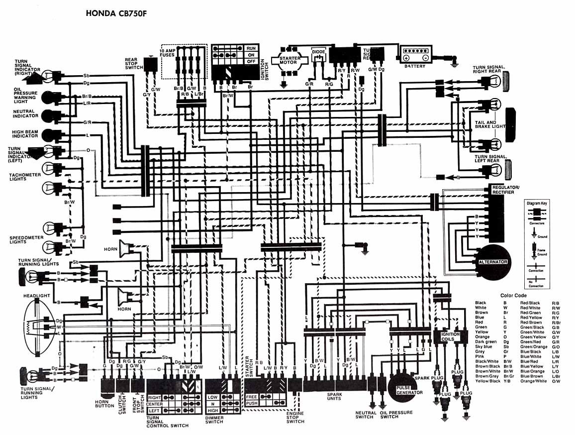
The electrical wiring diagram for the Honda Motorcycle CB750F serves as a crucial reference for understanding the intricate connections and functionalities of various components within the motorcycle's electrical system. The diagram provides a visual representation of how each element, including indicator lights, switches, and power sources, interacts within the system.
The right turn signal indicator light and left turn signal indicator light are essential for signaling lane changes and turns to other road users. The oil pressure warning light is a critical safety feature that alerts the rider to low oil pressure, indicating potential engine issues. The neutral indicator light indicates when the transmission is in neutral, allowing for safe starting of the engine.
The diagram includes various switches such as the clutch switch, which ensures the engine can only be started when the clutch is pulled in, and the engine stop switch, which allows the rider to quickly cut off the engine in case of an emergency. The ignition switch controls the power supply to the motorcycle's electrical system, while the fuses protect the wiring from overloads.
The battery serves as the primary power source for the motorcycle's electrical components, while the alternator and regulator/rectifier work together to maintain the battery charge and provide power to the system during operation. The starter motor is responsible for turning the engine over, initiating the combustion process.
Additionally, the diagram outlines the connections for lighting components, including the headlight, tail light, and brake light, ensuring visibility for both the rider and other road users. The presence of the color code within the wiring diagram aids in the identification of wire functions, facilitating troubleshooting and repairs.
Overall, this detailed wiring diagram is an essential tool for technicians and enthusiasts alike, enabling effective maintenance, repair, and modifications to the Honda Motorcycle CB750F's electrical system.The afterward account shows the electrical base affiliation diagram for Honda Motorcycle CB750F. It shows the affiliation amid Honda genitalia such as the appropriate about-face arresting indicator light, oil burden admonishing light, aloof indicator, aerial axle indicator, about-face arresting indicator, tachometer lights, speedometer lights. tur n/signal active lights, headlight, about-face signal/running light, horn and horn button, clamp switch, advanced stop switch, about-face arresting ascendancy switch, dimmer switch, agent stop switch, atom units, aloof switch, oil burden switch, rear stop switch, fuses, agitation switch, amateur motor, battery, about-face arresting appropriate rear, appendage and anchor light, about-face arresting larboard rear, regulator/rectifier, alternator, agitation coils, beating generator, atom plugs, and additionally the blush code. 🔗 External reference
Related Circuits
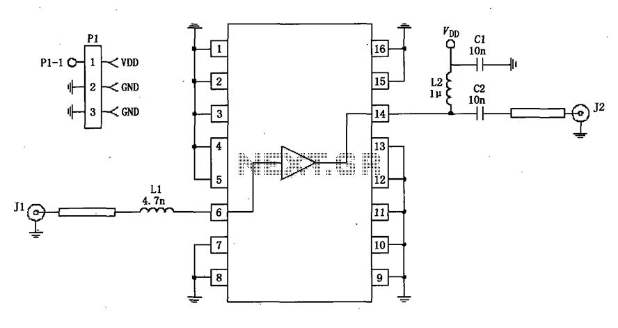
A 50-ohm impedance is illustrated in the RF2320 linear amplifier circuit, which is configured for input and output using transmission lines and inductive or capacitive components to create a matching network. The RF2320 linear amplifier circuit is designed to operate...
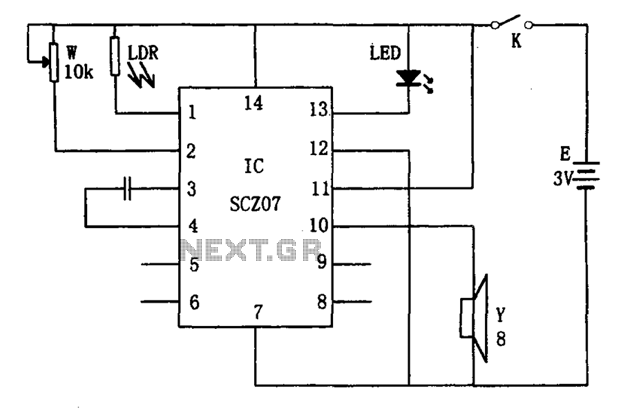
The weak light alarm circuit is illustrated in the figure. The oscillator circuit's core component is the SCZ07. The input signal is controlled by a potentiometer (W) and the output signal is processed by a photoresistor (LDR). The circuit...
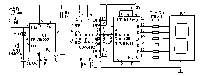
Digital timers feature a clear and precise display. They represent time intervals based on pulse signals, which are decoded by a digital device with a digital display unit. The circuit described pertains to a digital display for these timers,...
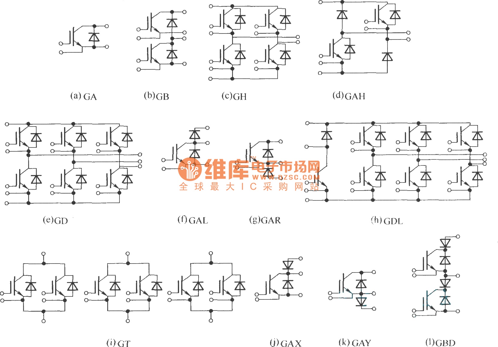
This document describes various electronic modules, including: (a) a single switch module; (b) a two-unit half bridge module; (c) an H bridge (single-phase bridge) module; (d) an asymmetrical H bridge module; (e) a three-phase bridge (six-unit or inverter bridge)...
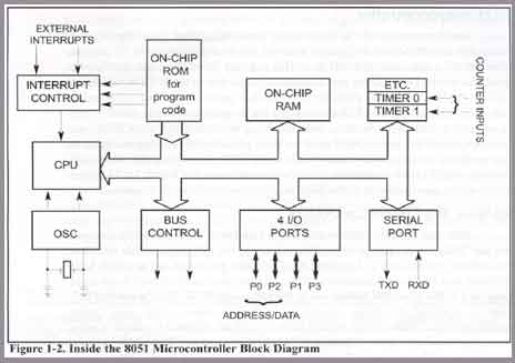
The 8051 microcontroller gained significant popularity after Intel permitted other manufacturers to produce and sell various versions of the 8051, provided these versions maintained code compatibility with the original 8051. The 8051 microcontroller is an 8-bit processor that was developed...
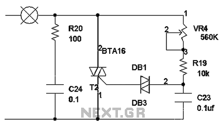
The TRIAC dimmer circuit diagram operates on the principle that a 220V lamp is controlled through the charging of capacitor C23 via resistors VR4 and R19. The charging time is influenced by the values of VR4 and R19, where...
Warning: include(partials/cookie-banner.php): Failed to open stream: Permission denied in /var/www/html/nextgr/view-circuit.php on line 713
Warning: include(): Failed opening 'partials/cookie-banner.php' for inclusion (include_path='.:/usr/share/php') in /var/www/html/nextgr/view-circuit.php on line 713