
Honda S90 Haynes Electrical Wiring
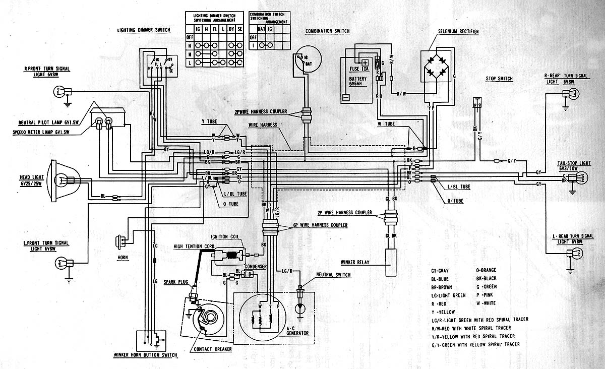
The Honda S90 electrical wiring diagram serves as a vital reference for understanding the interconnections and functionalities of the motorcycle's electrical system. The diagram includes various components such as the battery, ignition system, lighting, and fuse, which are essential for the operation of the motorcycle.
The battery provides the necessary voltage to power the electrical components, while the ignition system is responsible for starting the engine and ensuring proper combustion. The lighting system includes headlamps, tail lights, and indicators, which are crucial for visibility and safety during operation. The fuse acts as a protective device, preventing overload and potential damage to the electrical circuit by breaking the connection when excessive current flows.
The wiring diagram typically features a layout that indicates the color coding of wires, the positioning of connectors, and the routing of cables throughout the motorcycle. Each component is represented with standardized symbols, allowing for easy identification and troubleshooting. This schematic is instrumental for both maintenance and repair tasks, enabling technicians and enthusiasts to diagnose issues effectively and ensure the electrical system operates reliably.
Overall, the Honda S90 Haynes electrical wiring circuit diagram is an essential tool for anyone working on or maintaining this classic motorcycle, providing clarity and guidance for its electrical system.This circuit shows about Honda S90 Haynes Electrical Wiring Circuit Diagram. Features: shows the connection between Honda parts Component: fuse .. 🔗 External reference
Related Circuits
Do not forget to seal your wire splices with heat shrink tubing. It provides tensile strength to wires, is flame-retardant, and protects against fraying. Heat shrink tubing forms a protective, insulated, water-resistant covering over wiring splices, crimp terminals, and...
There are several sections on this website that provide information about track wiring. Part I discusses general wiring information, testing, and troubleshooting, while Part II details the actual wiring of the track. The menu on the right will guide...
A circuit for a remote control unit utilizes radio frequency signals to operate various electrical appliances. This remote control unit features four channels, which can be expanded to twelve. Unlike typical remote control circuits that rely on infrared light...
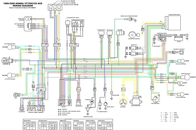
The following circuit illustrates the electrical circuit diagram for the Honda VT750C Ace. Features include a 745cc engine with a 52-degree V-twin configuration and two 36mm constant velocity carburetors. The Honda VT750C Ace electrical circuit diagram serves as a crucial...

The phase and neutral wires from the power source have already been connected to electrical appliances such as fans and light points. According to the UPS connection diagram, an additional phase wire should be connected to those appliances where...
PDS addresses the limitations of standardized measures to achieve uniform materials, designs, routing, installation, and construction, creating a clear structure that is easy to manage and maintain centrally. In modern buildings, cabling has become a trend and is considered...