
Horizontal Electric Engine

The model operates on the principles of electromagnetic induction, where the movement of the iron core within the coil generates a magnetic field that interacts with the current flowing through the coil. This interaction produces a force that drives the core in a reciprocating motion, akin to the operation of a steam engine but utilizing electrical energy instead of thermal energy.
The use of slotted opto switches provides precise control over the electromagnet's operation, allowing for real-time feedback and adjustment of the engine's speed. The integration of the 555 timers into the circuit provides a reliable means of generating the necessary control signals. The astable configuration of IC1 allows for continuous operation, while the monostable configuration of IC2 enables the detection of speed changes and the adjustment of the control voltage accordingly.
The circuit design emphasizes modularity and adaptability, as evidenced by the use of standard components such as the 555 timer and the power MOSFET, which are widely available and easy to integrate into various applications. The ability to adjust the speed via a potentiometer enhances the model's versatility, making it suitable for demonstrations or educational purposes.
Overall, this model serves as an innovative demonstration of electromagnetic principles and provides insights into the operation and control of electromechanical systems. The detailed circuit diagrams and accompanying photos facilitate a comprehensive understanding of the model's construction and functionality.Using the principles of a horizontal steam engine I constructed a model in which the steam cylinder is replaced by an electromagnet with a moving core. The construction details of the model are of little importance, as the photos give all the information you need.
The cylinder is replaced by an coil, while an iron core replaces the piston of a ste am engine. The construction details of both are shown in the photos below. If the core is placed about half of its length into the coil, and the current is then switched on, the core will be sucked right into the coil. The current will then be automatically switched off by the associated electronics. The core keeps on moving, due to the energy stored in the flywheel, until it comes out at the other end of the coil.
When the current is then switched on again the action repeats in the opposite direction. The core (piston) is pulled alternately backwards and forward thus forming a reciprocating engine. Two slotted opto switches are used to control the electromagnet and regulate its speed, placed as shown in the photos below. The slotted opto switches are mounted on the same printed circuit boards (PCBs) that I used in my Cliff Lift model.
The only difference is that one third of each has been cut off due to the proximity of the slotted opto switches to the gearwheel in this model. The first slotted opto switch switches the electromagnet current on and off using two shutters mounted on a gearwheel (Meccano part 95b) coupled to the flywheel.
The second slotted opto switch measures the speed of the engine using the teeth of the same gearwheel. This speed information controls the current through the coil and acts as a regulator. Figure 2 shows the block diagram of the system, and figure 3 shows the full circuit diagram. The circuit diagram can also be downloaded separately from the link below. IC1 is a 555 timer and it is configured as an astable. Using the Reset input (pin 4), the Output (pin 3) is switched on and off under the command of the On/Off slotted opto switch sensor.
The square wave signal at the output of the 555 drives a power MOSFET transistor BUZ11. A second 555 timer, IC2, is configured as a monostable. It is triggered by the Speed slotted opto switch sensor and transistor T1. The output pulses are integrated to form a DC component used as control voltage for IC1 (input into pin 5). The control voltage has the effect of changing the frequency and the duty cycle of the square wave signal output from pin 3.
The current through the coil will therefore vary from 0. 5A to 4A and so the engine will run at a constant speed. The speed can be set using a potentiometer to change the monostable time period of IC2. 🔗 External reference
Related Circuits
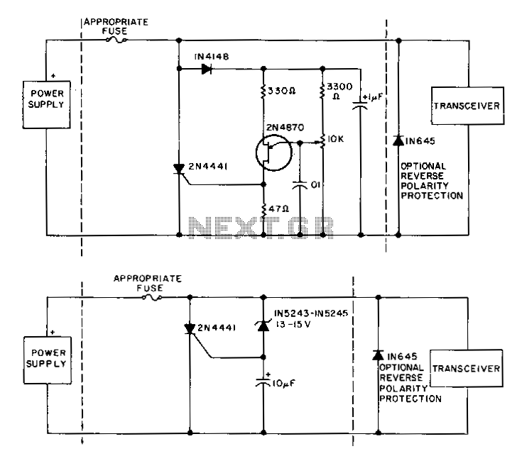
To prevent issues when using 12-V power supplies with mobile transceivers, particularly during a short-circuit failure of the series pass transistor, crowbar circuits offer protection by clamping the power line and blowing the fuse within microseconds of an overvoltage...
The OBO V20C functions as a lightning protection module, capable of handling a maximum lightning damage current of 40 kA. It includes a relay (k), a contactor (KM), a fuse (FU), and traffic lights (HL). The OBO V20C lightning protection...
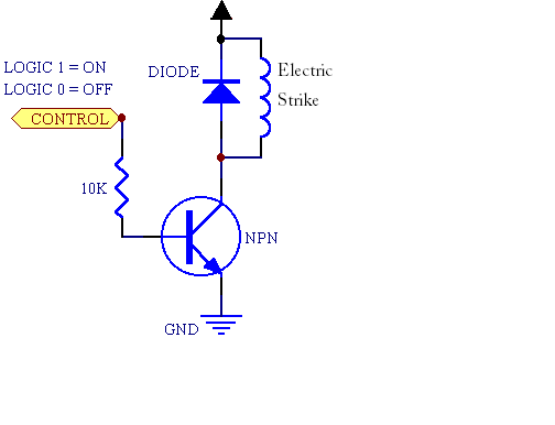
A fingerprint door lock system is being considered for implementation. The primary component is a fingerprint reader that, upon recognizing a valid fingerprint, will instruct an Arduino microcontroller to activate a locking mechanism for a predetermined duration. The locking...
The design is simple, tuneable, but no longer terribly useful. This design has a number of weaknesses; courtesy of Wilf Rigter, here are a few: The provided description indicates a circuit design that emphasizes simplicity and tunability, yet lacks practical...
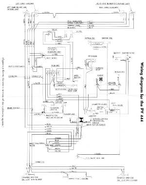
The following circuit illustrates the wiring diagram for the Volvo PV444, a vintage car electrical circuit. It provides an electrical understanding of this uni-body vehicle. The Volvo PV444 wiring diagram serves as a crucial reference for understanding the electrical system...
The fundamental issue presented is the perception that logic gates in a circuit seem to generate power from nothing, which contradicts the principles of physics. For instance, consider two NOT gates connected in series. It appears that the first...