
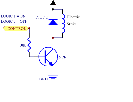
Electric strike with Arduino circuitry
The described fingerprint door lock system integrates several key components to create a secure and efficient access control mechanism. The fingerprint reader serves as the primary input device, capturing and processing biometric data to authenticate users. This reader is connected to an Arduino microcontroller, which acts as the central processing unit. Upon successful fingerprint verification, the Arduino sends a signal to the locking mechanism, activating it for a specified duration to allow entry.
The locking mechanism, an electric door strike, is designed to be compatible with standard door hardware and is powered by a 12-volt DC power supply, which provides sufficient current (2000mA) to ensure reliable operation. The selected power supply must be capable of delivering consistent voltage and current to both the fingerprint reader and the locking mechanism without fluctuations that could affect performance.
The term "12V Return" likely refers to the return path for the electrical current after it has passed through the locking mechanism. This return path is essential for completing the circuit and ensuring that the locking mechanism operates correctly. It is crucial to connect this return line appropriately to the power supply to avoid potential issues with the system's functionality.
In the event that an electromagnet is considered as an alternative to the electric strike, it is important to ensure that the electromagnet's specifications align with the power supply and control logic of the Arduino. The electromagnet would require a similar voltage and current rating to function effectively. Additionally, the control circuit may need to be modified to accommodate the characteristics of the electromagnet, such as incorporating a relay or transistor to handle the inductive load.
Overall, this fingerprint door lock system has the potential to provide enhanced security and convenience. Careful attention to component compatibility, circuit design, and power management will be essential for successful implementation.A fingerprint door lock, and the only thing that`s stopping me from purchasing the components is knowing if my setup is going to work or not. Is this an acceptable setup For the actual fingerprint reader, I was going to use this one, , which upon receiving the correct fingerprint, tell the Arduino to send power to the lock to unlock it for a certain amount of seconds.
The strike that I will be using is similar to the " Electric Door Strike for Schlage Locks, " and the power supply will be similar to the " Linear Corporation AAE00381 12-Volt DC 2000ma Power Supply. " Do these schematics make sense After discussing this with HikeOnPast below, I believe I copied his schematics correctly.
I`m not sure what he meant by "12V Return" from the strike but I assumed it is the same as sending it back to the power. Would the above work with an electromagnet substituted for the strike (I`m assuming yes, I would just need to find parts that are compatible with the magnet)
🔗 External reference
Related Circuits
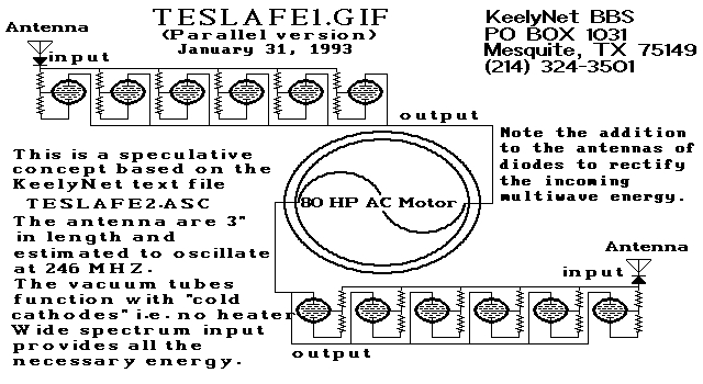
Two schematic diagrams illustrate a series and a parallel circuit configuration that Tesla may have utilized. The components featured are the 70L7GT Half Wave Rectifier tubes, which are surprisingly still available today. While there is an interest in accessing...
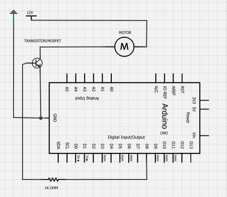
The BC547 transistor has a maximum operating current of 100 mA and a maximum voltage rating of 65 volts. When oriented with the label facing the viewer, the three terminals from left to right are collector, base, and emitter....
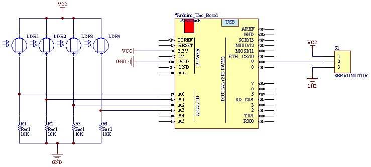
The movement of the servo is determined by the output values of the photoresistors. The impedance of these sensors changes with the amount of light incident upon them. The servo's position shifts towards the sensor that detects less light....
A piezoelectric sounder (self-drive type) consists solely of a piezoelectric diaphragm with a feedback electrode and is utilized in conjunction with an external drive circuit. The drive circuit for both types of sounders is a simple configuration comprising one...
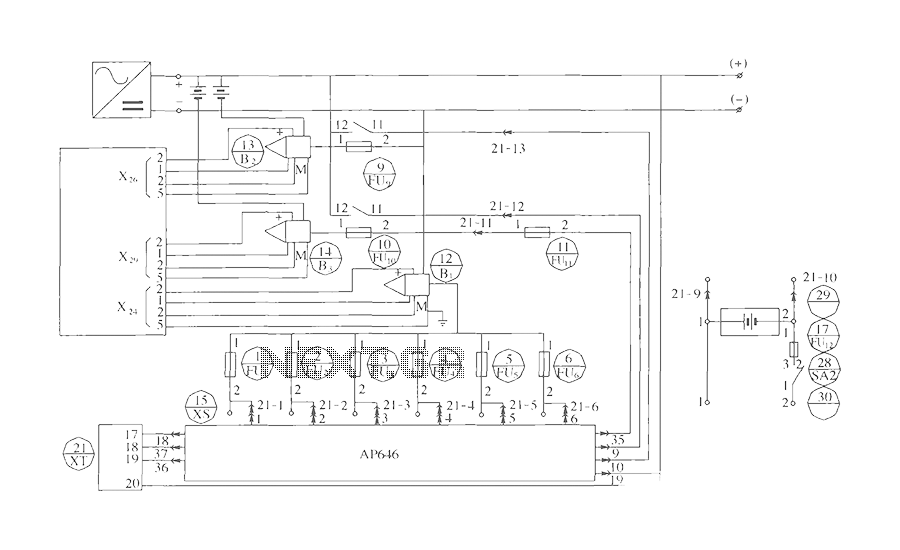
The components include B2 (13) and B3 (14) designated for the Hall current sensor; FU9 (9) and FU10 (10) serve as fuses; an AP646 alarm signal is connected to the fuse board; terminals X24, X26, and X29 function as...
This project implements a network-connected water level sensor that measures the water level in the sump pit of a house. It is connected to the home network and reports the water level by broadcasting UDP packets, allowing any computer...