
Wiring Diagram And Electrical Circuit For Volvo PV444
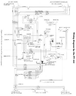
The Volvo PV444 wiring diagram serves as a crucial reference for understanding the electrical system of this classic automobile. This vintage car features a uni-body construction, which integrates the body and chassis into a single component, enhancing structural integrity and reducing weight.
The wiring diagram typically includes various components such as the ignition system, lighting, battery connections, and the alternator. Each component is represented with clear symbols and connections, allowing for easy identification and troubleshooting.
The ignition system in the PV444 consists of the ignition coil, distributor, and spark plugs. The wiring diagram outlines the connections between these components, ensuring proper voltage supply and timing for optimal engine performance.
The lighting system includes front and rear headlights, turn signals, and interior lights. The diagram specifies the wiring paths and the fuse protection for each circuit, which is essential for maintaining safety and functionality.
Furthermore, the battery connections are depicted, showing how the battery connects to the starter motor and the electrical system. The alternator's role in charging the battery while the engine is running is also highlighted, ensuring the vehicle remains operational.
Understanding this wiring diagram is vital for restoration projects or routine maintenance of the Volvo PV444, as it provides essential insights into the electrical layout and helps in diagnosing issues that may arise over time.The following circuit shows about Volvo PV444 Wiring Diagram Vintage Car Electrical Circuit. Features:electrical understanding of this uni-body .. 🔗 External reference
Related Circuits

This circuit utilizes the Mitsubishi M65830 Digital Delay chip, which has proven to be simple and effective for applications requiring a fixed delay. The serial data necessary for achieving various delay settings is not readily available and would significantly...
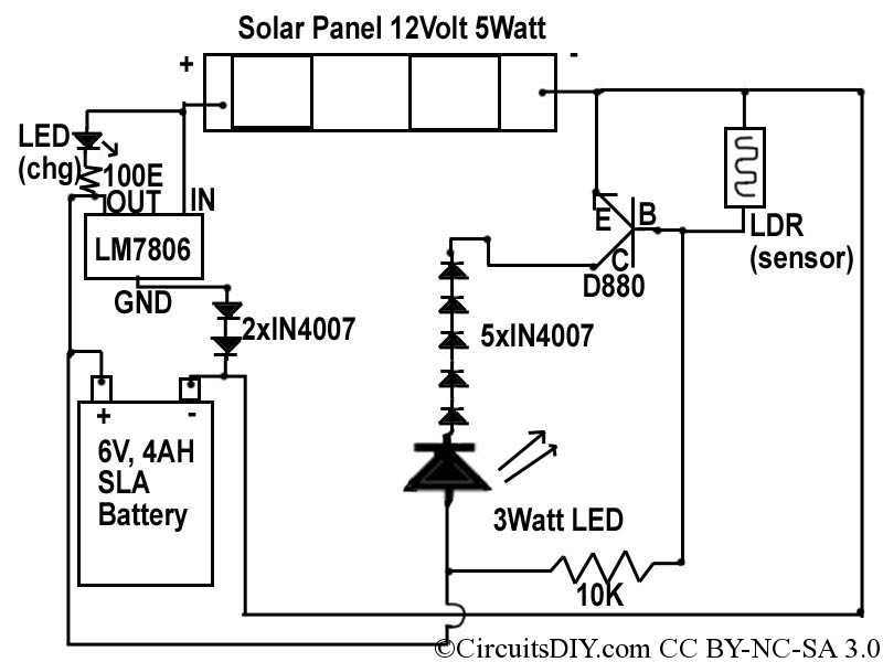
This document discusses a simple solar LED circuit. Solar panels range from 12 volts and 3 watts to larger sizes. To store energy, a 12-volt battery is required. The preferred choice is a sealed lead-acid (SLA) sealed maintenance-free (SMF)...
The following circuit illustrates how to build a variable DC power supply circuit. This circuit is based on the 7805 IC. Features: other output is ... The variable DC power supply circuit utilizing the 7805 integrated circuit (IC) is designed...
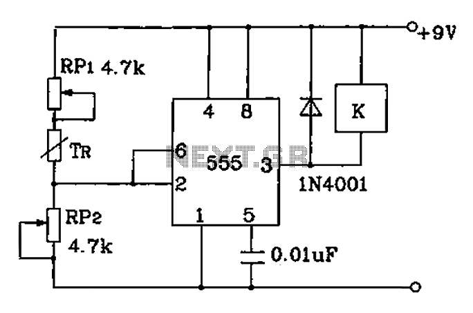
Adjust RP1 and RP2 to set the preset temperature control point. The 555 circuit is configured as a Schmitt inverter circuit that automatically controls a relay device. This forms part of the T-121 temperature control circuit, which includes a...
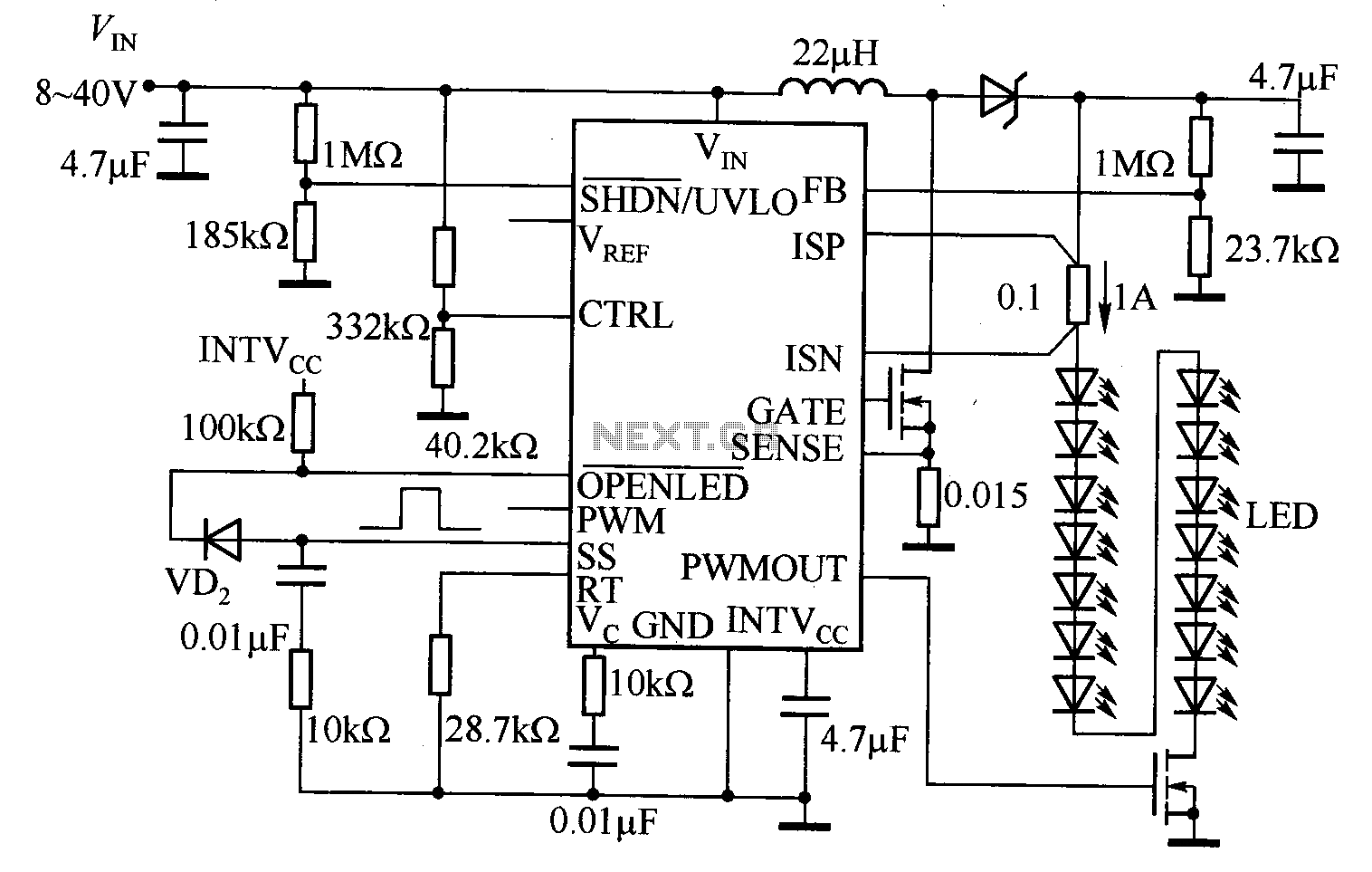
The LT3755 is utilized for high-side current sensing in LED strings, enabling flexible programming and control. It supports a PWM input that allows for a dimming ratio of up to 3000:1, while the CTRL input offers additional analog dimming...
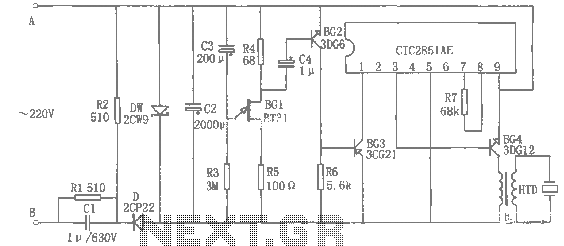
The rice cooker notification circuit operates as follows: When the rice cooker is in operation, both terminals A and B have a voltage of 0, meaning the entire circuit remains inactive. In the event that the rice cooker runs...
Warning: include(partials/cookie-banner.php): Failed to open stream: Permission denied in /var/www/html/nextgr/view-circuit.php on line 713
Warning: include(): Failed opening 'partials/cookie-banner.php' for inclusion (include_path='.:/usr/share/php') in /var/www/html/nextgr/view-circuit.php on line 713