
Host computer automatic temperature control circuit

The automatic temperature control circuit described is essential for maintaining optimal operating conditions in high-performance computing environments. The implementation of the LM339 voltage comparator allows for precise monitoring of the internal temperature through the thermistor. The thermistor's resistance decreases as the temperature rises, enabling the circuit to detect when the temperature surpasses the predetermined threshold. The RP variable resistor serves to fine-tune the activation point of the fans, ensuring that they engage at the most effective temperature for cooling.
The circuit's design should consider the placement of the fans to maximize airflow efficiency. The exhaust fan (M1) should be positioned to expel hot air from the top or rear of the chassis, while the intake fan (M2) should draw cooler air from the front or side, creating a continuous flow of air through the system. This arrangement not only cools the CPU and graphics card effectively but also helps in maintaining the overall stability and performance of the machine during intensive tasks.
Additionally, it is advisable to incorporate filters on the intake fan to prevent dust accumulation inside the chassis, which can hinder airflow and lead to overheating. Regular maintenance and monitoring of the system's thermal performance can further enhance reliability and longevity. The circuit's simplicity and effectiveness make it a valuable addition to any computer system, particularly those used for demanding applications.Computer when you run large-scale software or games machine in the heat will increase the temperature inside the machine so that, especially in the hot summer when more obvious. While the machine is installed CPU and graphics card fan, but the hot air circulation is poor and not able to be immediately removed to the machine, so that the internal temperature is relatively high. To solve this problem, as shown in the calculation of the host machine automatic temperature control circuit can be set free temperature control point, when the internal temperature is higher than the set temperature intake and exhaust air fan operate simultaneously, the dryer exhaust heat air in a timely manner out, while the man-machine suction cold air outside, so air circulation inside the machine, so as to achieve the purpose of cooling.
RT, R, and four voltage comparator LM339 constitute a temperature sensing circuit, RT is a positive temperature coefficient thermistor, first RT disposed of hot water 40 ~ 45 , the carefully adjusted RP, just let the fan is rotated so far; the adjustment is completed after the entire electrical circuit board installed in a suitable place inside the chassis, power supply connected directly to the computer's + 12V power supply, fan Ml, M2 - one for exhaust gas fan, the other for the intake fan, are mounted inside the chassis as empty position exhaust fan and intake fan. The role of the heart is to allow the output of a certain backlash.
Related Circuits
The two circuits di atas illustrate opening a relay contact a short time after the ignition or light switch is turned off. The capacitor is charged and the relay is closed when the voltage at the diode anode rises...
Samsung C3330 Circuit Diagram Download Manual PDF Download. The Samsung C3330 circuit diagram serves as a comprehensive reference for understanding the electronic architecture of the device. This schematic provides detailed insights into the interconnections between various components, including the microcontroller,...
The Implantable Lamp (A3024) is a radio-controlled lamp powered by a battery. Once encapsulated in epoxy and silicone, it is waterproof and compact, allowing it to be implanted in an animal. The A3024 can theoretically be activated by any...
The intention was to develop a morning exercise machine, but the challenge was the absence of a suitable high-power amplifier. Since the exercise machine operates on battery power, the search for a solution persisted for several months. Eventually, the...
The LTC3731H is a linear three-phase step-down voltage regulation power control unit from the company, capable of driving N-channel MOSFETs. It operates within a temperature range of up to 140°C and supports a control frequency of up to 600...
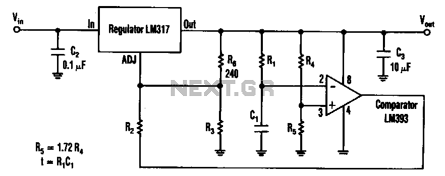
The timed two-voltage circuit can start and run a small DC motor or solenoid. The input voltage to the LM317 three-terminal regulator ranges from 5 to 40 V, and the output voltage can range from 2 to 36 V....