
Very simple Delay circuit!

The time delay for the common emitter will be approximately 3 time constants or 3*R*C. The capacitor/resistor values can be worked out from the relay coil current and transistor gain. For example, a 120 ohm relay coil will draw 100 mA at 12 volts and assuming a transistor gain of 30, the base current will be 100/30 = 3 mA. The voltage across the resistor will be the supply voltage minus two diode drops or 12-1.4 = 10.6. The resistor value will be the voltage/current = 10.6/0.003 = 3533 or about 3.6K. The capacitor value for a 15 second delay will be 15/3R = 1327 uF. We can use a standard 1000 uF capacitor and increase the resistor proportionally to get 15 seconds.
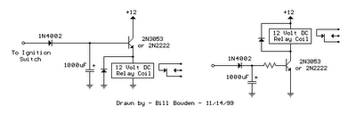
The described circuits serve to delay the opening of a relay contact after the ignition or light switch is turned off, utilizing a capacitor to provide a timed delay. In the first circuit, which employs a common collector configuration (also known as an emitter follower), the relay is activated when the voltage at the diode anode reaches 12 volts, allowing the capacitor to charge. This design simplifies the circuit by eliminating the need for a series resistor with the transistor base, though it results in a lower voltage across the relay coil, approximately 11 volts due to the forward voltage drops across the diodes.
In contrast, the second circuit utilizes a common emitter configuration, which allows for the full supply voltage to be applied across the relay coil during the majority of the delay time. This configuration enhances the reliability of the relay operation by ensuring adequate voltage levels for both pull-in and drop-out conditions. However, it necessitates an additional resistor in series with the transistor base to control the base current. The design of this resistor is critical, as it can be adjusted to achieve the desired delay time by manipulating the capacitor value in conjunction with the resistor.
The time delay is calculated as approximately three time constants (3τ), where τ is the product of the resistance (R) and capacitance (C). For instance, if a relay coil has a resistance of 120 ohms and draws a current of 100 mA at 12 volts, the required base current can be determined based on the transistor's current gain. With a gain of 30, the base current would be approximately 3 mA. The voltage across the base resistor is derived from the supply voltage, minus the two diode forward voltage drops, yielding about 10.6 volts. The appropriate resistor value can thus be calculated to be around 3.6 kΩ.
To achieve a specific delay, such as 15 seconds, the capacitor value can be derived from the formula for time delay. In this case, a calculated capacitance of approximately 1327 µF is needed. A standard capacitor of 1000 µF can be employed, with the series resistor adjusted accordingly to maintain the desired delay duration. This careful selection of components ensures that the relay operates as intended, providing a reliable solution for controlling devices post-ignition or light switch operation.The two circuits di atas illustrate opening a relay contact a short time after the ignition or ligh switch is turned off. The capacitor is charged and the relay is closed when the voltage at the diode anode rises to 12 volts.
The circuit on the left is a common collector or emitter follower and has the advantage of one less part since a resistor is not needed in series with the transistor base. However the voltage across the relay coil will be two diode drops less than the supply voltage, or about 11 volts for a 12.5 volt input.
The common emitter configuration on the right offers the advantage of the full supply voltage across the load for most of the delay time, which makes the relay pull-in and drop-out voltages less of a concern but requires an extra resistor in series with transistor base. The common emitter (circuit on the right) is the better circuit since the series base resistor can be selected to obtain the desired delay time whereas the capacitor must be selected for the common collector (or an additional resistor used in parallel with the capacitor).
The time delay for the common emitter will be approximately 3 time constants or 3*R*C. The capacitor/resistor values can be worked out from the relay coil current and transistor gain. For example a 120 ohm relay coil will draw 100 mA at 12 volts and assumming a transistor gain of 30, the base current will be 100/30 = 3 mA. The voltage across the resistor will be the supply voltage minus two diode drops or 12-1.4 = 10.6. The resistor value will be the voltage/current = 10.6/0.003 = 3533 or about 3.6K. The capacitor value for a 15 second delay will be 15/3R = 1327 uF. We can use a standard 1000 uF capacitor and increase the resistor proportionally to get 15 seconds. 🔗 External reference
Related Circuits
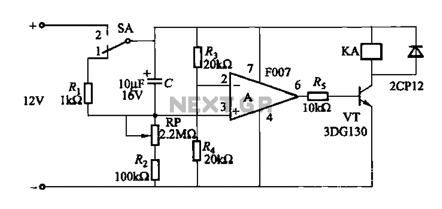
A delay circuit utilizing an operational amplifier functions as a comparator, providing high timing accuracy. The timer's delay range is from 1 to 30 seconds. The delay time is determined by resistors Ri, RP, and capacitor C. By adjusting...
The two circuits illustrated show the operation of opening a relay contact shortly after the ignition or light switch is turned off. A capacitor is charged, and the relay remains closed until the voltage at the diode anode rises...

The circuit utilizes a 555 timer IC to create a lighting group delay effect, as illustrated in Figure 2-46. It consists of the 555 IC along with a resistor and capacitor configuration that establishes the delay. The circuit remains...
The diagram illustrates a simple and efficient receiver designed for activating garage doors, starter motors, alarms, warning systems, and various other applications. The SCR utilized in this circuit features an extremely low trigger current of 30 µA, requiring only...
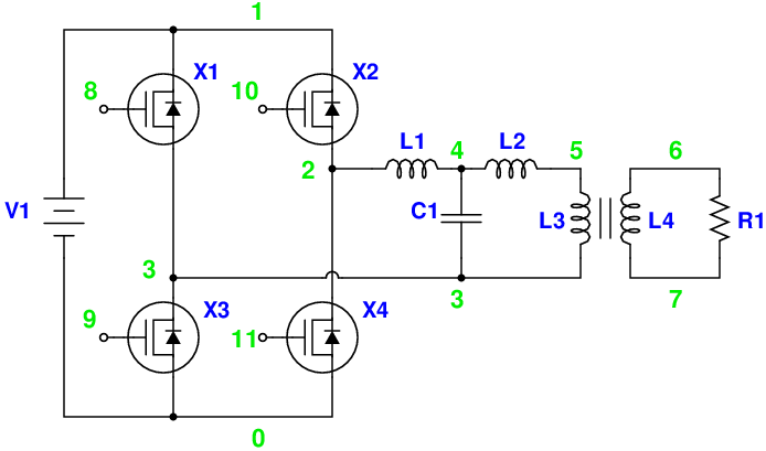
Magic Sinewave Analysis using SPICE and a Simple Inverter Circuit. This document discusses the analysis of a sinewave signal generated by a simple inverter circuit using SPICE simulation software. The inverter circuit is designed to convert a DC input voltage...
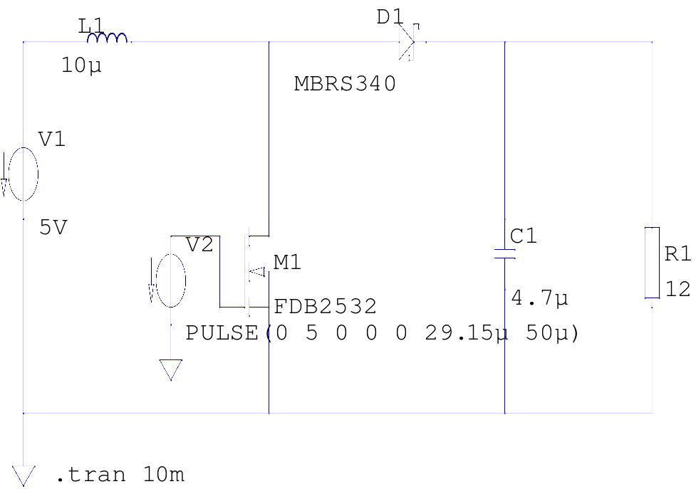
The supply voltage is 5V, and the goal is to increase it to 12V with a load current of 1A, resulting in an output power of 12W. A switching frequency of 20kHz has been selected, requiring a duty cycle...
Warning: include(partials/cookie-banner.php): Failed to open stream: Permission denied in /var/www/html/nextgr/view-circuit.php on line 713
Warning: include(): Failed opening 'partials/cookie-banner.php' for inclusion (include_path='.:/usr/share/php') in /var/www/html/nextgr/view-circuit.php on line 713