
How does an astable multivibrator LED blinking circuit work
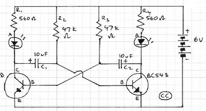
The circuit described involves a sequential LED blinking mechanism, which can be achieved through a simple astable multivibrator configuration using transistors. The primary components typically include two light-emitting diodes (LEDs), a capacitor, resistors, and two NPN transistors.
In this configuration, the capacitor is crucial for timing. When the circuit is powered, the capacitor begins to charge through a resistor. This charging process causes the voltage across the capacitor to rise gradually. Once the voltage reaches a certain threshold, it turns on the first NPN transistor, allowing current to flow through the first LED, causing it to illuminate.
As the capacitor continues to charge, it eventually reaches a point where it can no longer sustain the first transistor's conduction, causing the transistor to turn off. This results in the first LED turning off. The discharge path for the capacitor is typically through the second transistor, which is connected in such a way that when the first transistor turns off, the second one turns on, allowing current to flow through the second LED.
The timing of the LED blinking is determined by the values of the resistors and the capacitor used in the circuit. By adjusting these components, one can control the rate at which the LEDs blink in sequence. The transistors serve as electronic switches that control the flow of current to each LED based on the charge state of the capacitor, thereby enabling the sequential blinking effect. This arrangement not only provides a visual indication of the circuit's operation but also serves as a fundamental demonstration of capacitor charging and discharging principles in electronics.Blinks 2 LEDs timely in sequence. Will somebody explain its working I know that capacitor will charge and during the charging the LED will off and whenthey discharge they will on the LED. But why transistor are there 🔗 External reference
Related Circuits
It is based on an LM2917 and an SCR, which has the advantageous characteristic of preventing mis-timed sparks, a highly desirable feature for high-output rotary engines. When the engine reaches the rev limit during acceleration, the transition is smooth...
This project involves a straightforward soil moisture detection circuit that utilizes only four components and operates with a 3-volt battery. The circuit is designed to identify the presence of moisture in the soil of any plant and activate an...
What value of potentiometer should be used for the volume control of this audio amplifier circuit, and where should it be connected? Thank you. In audio amplifier circuits, the choice of potentiometer value for volume control is crucial for achieving...
The TDA8444 is a digital-to-analog (D/A) converter integrated circuit (IC) produced by Philips. It is designed to convert digital signals into analog signals. The TDA8444 IC utilizes a 16-pin dual in-line package, with specific pin functions and data outlined...
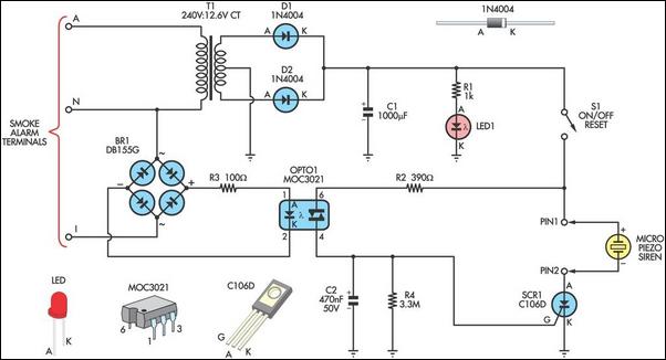
This alarm circuit is designed to monitor a mains-powered smoke detector located in a shed used for dog kennels. It ensures complete isolation from the mains, allowing low-voltage (12V) cabling to connect to the alarm circuit situated inside the...
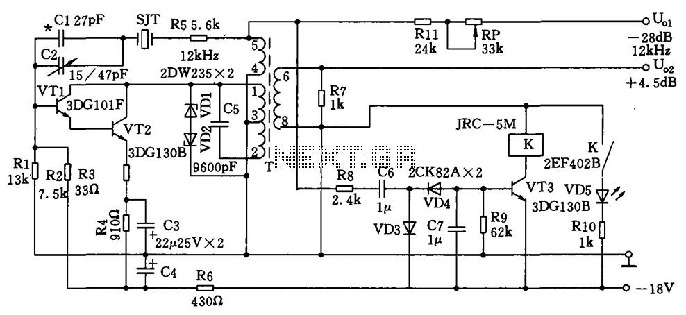
The circuit depicted is a 12 kHz intermediate frequency oscillator designed for an alarm system. It employs a variable feedback oscillation circuit where the oscillation frequency is primarily determined by a quartz crystal. Capacitors C1 and C2 are used...
Warning: include(partials/cookie-banner.php): Failed to open stream: Permission denied in /var/www/html/nextgr/view-circuit.php on line 713
Warning: include(): Failed opening 'partials/cookie-banner.php' for inclusion (include_path='.:/usr/share/php') in /var/www/html/nextgr/view-circuit.php on line 713