
plant soil moisture tester circuit
The soil moisture detection circuit consists of the following components: a moisture sensor, a potentiometer (R2), an LED, and a resistor. The moisture sensor is typically a pair of conductive electrodes that are inserted into the soil. When the soil is moist, the conductivity between the electrodes increases, allowing current to flow through the circuit.
The potentiometer R2 serves as a variable resistor that adjusts the sensitivity of the moisture sensor. By changing the resistance value, the user can set the moisture level at which the LED will illuminate. This feature provides flexibility, enabling the circuit to cater to different types of plants with varying moisture requirements.
The LED acts as a visual indicator; it will light up when the moisture level exceeds the set threshold. This simple yet effective design allows for easy monitoring of soil moisture, helping to prevent overwatering or underwatering of plants. The entire circuit can be powered by a 3-volt battery, ensuring portability and ease of use in various gardening applications.
Overall, this soil moisture circuit is an excellent tool for gardening enthusiasts, combining simplicity, functionality, and efficiency in plant care.A very simple and useful project of soil moisture circuit. The circuit is using only four components and a 3 volt battery. The circuit will detect if there is water in the soil of any plant and light up the LED. The resistor R2 is a potentiometer to adjust the level on which you want to make the LED on. 🔗 External reference
Related Circuits

The coil must invert the signal a second time to ensure that the feedback is positive, which will cause the circuit to oscillate on and off. In electronic circuits, particularly in oscillator designs, the feedback mechanism plays a crucial role...

When an alarm or notification is needed after ten minutes, the circuit illustrated below can be utilized. This circuit is essentially a monostable multivibrator based on the IC NE555. When the reset push button is pressed, the green LED...
Probably the easiest way of doing automatic switch off is with relay logic. In the diagram, the box marked RL1 is the coil, the 2 in the coil box tells you there are two sets of contacts somewhere on...
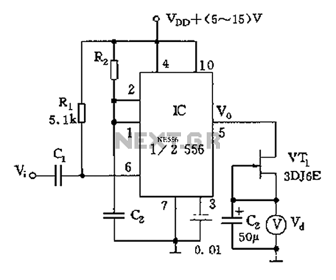
The circuit utilizes switch contacts that are proportional to the speed pulse signal Vi. A differential signal is fed into the trigger side of an integrated circuit (IC), specifically a 555 timer configured in monostable mode (1/2 556), to...

Basic features include an internal 512k-bit EEPROM, allowing for continuous recording and playback at any time, with long-term retention of voice data after power loss. The voice recording time is 20 seconds, and it supports segmented recording and playback....
The controllable multivibrator, as illustrated in figure 14-40, consists of a 555 timer along with resistors RA, RP1, and capacitor C1. The oscillation frequency is influenced by the control voltage applied to pin 5. This control voltage is determined...