
How Does DC to AC Inverter Circuit Works

The DC to AC inverter operates by utilizing a power conversion circuit that typically includes a signal generator, a power amplifier, and filtering components. The signal generator produces a square wave signal at a frequency of 60 Hz, which is then amplified by the power amplifier circuit. The output of the amplifier is a square wave voltage, which, while suitable for some applications, may not be ideal for sensitive electronic devices that require a pure sine wave for optimal performance.
To achieve a pure sine wave output, a more complex filtering system is employed. This system usually consists of passive components such as inductors and capacitors arranged in a specific configuration to form a high-pass filter. The primary purpose of this filter is to remove harmonics and high-frequency noise from the square wave output, resulting in a cleaner sine wave signal that better mimics the characteristics of utility-supplied AC power.
In practical applications, the inverter must also include protective measures to handle overcurrent and overheating conditions, ensuring the longevity and reliability of the system. Additionally, some inverters may incorporate feedback mechanisms to monitor output voltage and adjust the operation of the inverter in real-time, enhancing performance and efficiency.
Overall, the design and implementation of a DC to AC inverter require careful consideration of the desired output waveform, efficiency, and the specific requirements of the load it will serve. The choice between a square wave and a pure sine wave inverter will depend on the application and the sensitivity of the connected devices.DC to AC inverter`s function is to convert Direct Current (DC) voltage to Alternating Current (AC) voltage. DC to AC inverter is commonly used for converting High Voltage DC (HVDC) transmission voltage back to AC, and for converting the DC output voltage of a photovoltaic (PV) solar panel to suitable AC voltage.
The output AC voltage of the invert er can be a 60 Hz square wave or a pure sine wave. Of course, an inverter with pure sine wave output is more expensive than with a square wave output because of additional filters used. Basically, the power amplifier circuit just amplifies the output 60 Hz signal of the signal generator to approximately 24 V (peak-to-peak) square wave voltage.
If this is to be use to convert a DC voltage to AC like in PV system or in HVDC to AC conversion, the DC voltage input will be connected in the DC 24V terminals. Note that the above circuit doesn`t have a filter yet to filter out the high frequency component of the square wave to come up with a pure sine wave signal.
At load side, the voltage should like this; In commercially available DC to AC inverters, a sophisticated filter is used to produce a pure sine wave output. These kind of filters is, basically, a high pass filter that completely remove all of the signal with frequencies more than 60 Hz.
🔗 External reference
Related Circuits
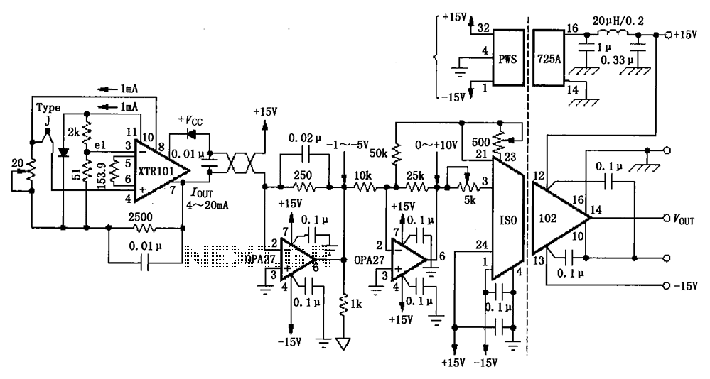
The circuit depicted in the figure features the ISO102 and XTR101 components, forming an isolated remote transmitter circuit equipped with isolated thermocouple cold-junction compensation. The circuit comprises four main parts: the current loop amplifier XTR101, the isolation amplifier ISO102,...
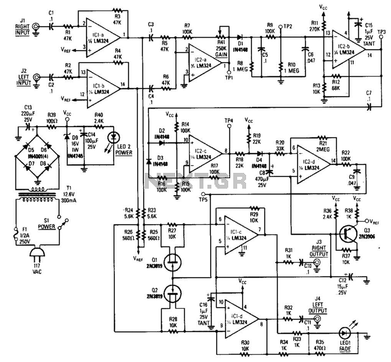
The LR inputs are summed, processed, and then drive a comparator. This comparator detects levels and generates transitions when audio inputs exceed or fall below predetermined thresholds. The frequency of these transitions, which correspond to rapid volume changes, is...
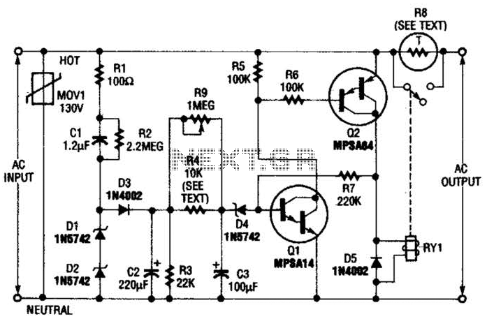
Q1 is an NPN Darlington transistor, and Q2 is a PNP Darlington transistor. MOV1 is a metal-oxide varistor, while R8 is a thermistor used for limiting inrush current. This circuit is designed to limit AC line current to a...
This circuit can be directly connected to CD players, tuners, and tape recorders. It requires the addition of a 10K logarithmic potentiometer (dual gang for stereo) and a switch to accommodate various sources. Proper grounding is crucial to eliminate...
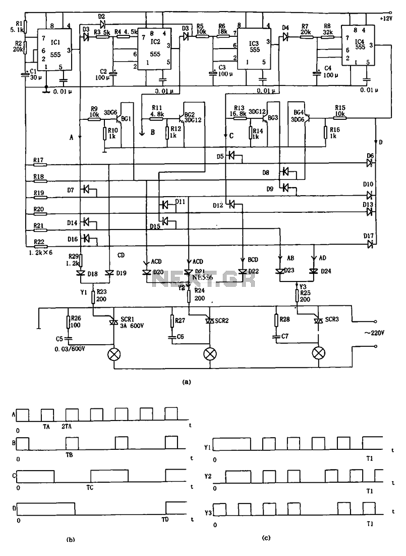
The decorative lamp control circuit is illustrated in the figure. The controller comprises a pulse generator, a frequency divider, a matrix circuit, and a thyristor control circuit. Components IC1, R1, R2, C1, and others form a multivibrator where the...
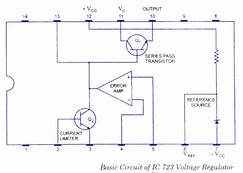
The working and block diagram of the IC 723 Voltage Regulator is provided along with the circuit diagram and applications. The IC 723 is a voltage regulator integrated circuit that is widely used for providing a stable output voltage. It...