
Having a cold junction compensation Remote Isolated Thermocouple transmitter circuit diagram ISO102 XTR101

The isolated remote transmitter circuit is designed to facilitate accurate temperature measurements in environments where electrical noise may interfere with signal integrity. The J-type thermocouple serves as the primary sensing element, providing reliable temperature readings. The XTR101, functioning as a current loop amplifier, is critical for converting the thermocouple's voltage output into a standard 4 to 20 mA current signal, which is widely used in industrial applications for its robustness against noise and signal degradation over long distances.
The OPA27 operational amplifier is employed to convert the current signal into a corresponding voltage signal, which is essential for further processing. The transformation to a voltage signal within the range of -1 to -5 V is particularly useful for interfacing with other control systems or data acquisition devices. The subsequent amplification through the ISO102 isolation amplifier ensures that the output remains stable and unaffected by potential ground loops or interference from surrounding electrical equipment.
Furthermore, the inclusion of adjustable potentiometers allows for fine-tuning of the circuit's performance. The 500-ohm potentiometer enables precise offset voltage adjustment, ensuring that the output accurately reflects the thermocouple's readings. Meanwhile, the 5k-ohm potentiometer allows for gain adjustments, providing flexibility in adapting the circuit to various measurement ranges and requirements.
The PWS725A isolated power supply is a vital component, providing the necessary power to the ISO102 amplifier while maintaining electrical isolation between different parts of the circuit. This isolation is crucial for preventing interference and ensuring the reliability of the signal transmission.
Overall, this circuit exemplifies a sophisticated design approach, integrating multiple components to achieve precise temperature measurement and transmission with enhanced noise immunity, making it suitable for a variety of industrial and environmental monitoring applications. As shown in FIG grounds ISO102 and XTR101, op amp, isolated remote transmitter circuit having isolated thermocouple cold-junction compensation constituted power. The circuit co nsists of four parts: the current loop amplifier XTR101, isolation amplifier ISO102, and isolated power operational amplifier OPA27 PWS725A. Using J-type thermocouple temperature detected at the scene, the temperature signal is converted to a voltage signal input XTR101, XTR101 by the amplified and converted into 4 ~ 20mA current output, through the twisted-pair transmission, input op amp OPA27.
OPA27 current signal into the op amp input voltage signal -1 ~ -5V, and then after another OPA27 inverting input is amplified by ISO102, ISO102 isolation amplifier output after which the 500 potentiometer used to adjust the offset voltage, 5k potentiometers to adjust the gain. PWS725A isolated power supply for the isolated primary and secondary side power amplifier ISO102 provided respectively.
The characteristics of this circuit is J-type thermocouple temperature detection and transmission site amplification and processing and control circuit isolation, improved anti-jamming capability of long-distance transmission signal circuits.
Related Circuits
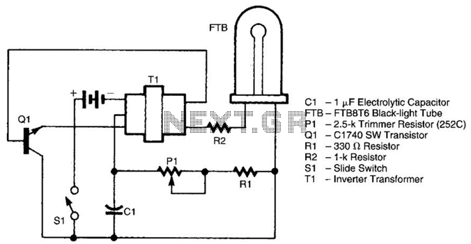
The battery-operated black light utilizes a U-shaped, unfiltered black-light tube, which requires approximately 250 Vac for operation. To generate the 250 Vac from a 6-V battery, the circuit employs a one-transistor blocking oscillator that drives a ferrite inverter transformer....
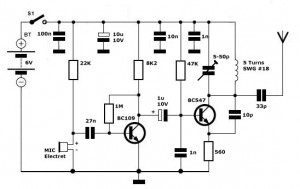
Simple FM Transmitter Circuit This simple FM transmitter circuit was built using a transistor with a transmission distance of about 300m around your home. The simple FM transmitter circuit utilizes a transistor to modulate audio signals onto a radio frequency...
This low-cost project enables audio reproduction from a television without disturbing others. It eliminates the need for wired connections between the TV and loudspeakers. Instead, it utilizes invisible infrared light to transmit audio signals from the TV to the...
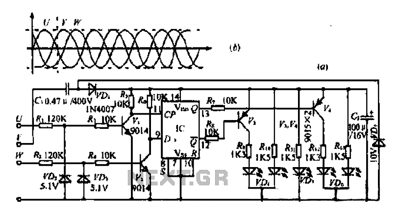
The three-phase voltage waveform diagram illustrates that when one phase voltage transitions from positive to negative across the zero point, the subsequent phase voltage becomes positive while the third phase remains negative. The U terminal voltage is positive when...
The White's Classic I was a straightforward and user-friendly metal detector, making it suitable for entry-level enthusiasts. It featured a simple design with only an on/off switch and a discriminator adjustment knob. Although it lacked depth, it was capable...
Convert a used CFL into a power-saving LED lamp circuit that consumes only 50mA. This gadget can be used in applications like a night light, table lamp, etc. The project involves redesigning a compact fluorescent lamp (CFL) to function as...