
how H-brigde is working

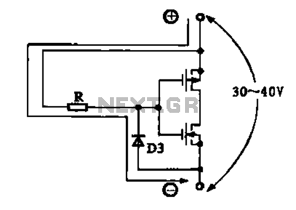
An H-bridge is a specific type of electronic circuit that enables a voltage to be applied across a load in either direction. This configuration is commonly used to control the direction of motors, particularly in applications such as robotics and automation.
The H-bridge gets its name from the arrangement of its components, which resembles the letter "H." It typically consists of four switches (transistors or MOSFETs) arranged in a bridge configuration. The switches are labeled as S1, S2, S3, and S4 for clarity.
To operate the H-bridge, the following states can be achieved:
1. **Forward Rotation**: To drive the motor in one direction, S1 and S4 are closed (turned on), while S2 and S3 remain open (turned off). This allows current to flow from the positive voltage supply through S1, then through the motor, and finally through S4 to ground.
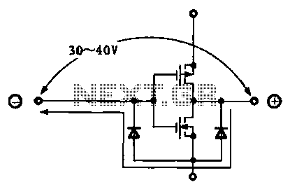
2. **Reverse Rotation**: To reverse the motor's direction, S2 and S3 are closed, while S1 and S4 are open. In this state, current flows from the positive supply through S2, through the motor in the opposite direction, and then through S3 to ground.
3. **Braking**: To stop the motor quickly, both S1 and S2 can be closed simultaneously, or both S3 and S4 can be closed. This creates a short circuit across the motor terminals, allowing the back electromotive force (back EMF) generated by the motor to dissipate quickly, thus stopping the motor.
4. **Coasting**: When all switches are open, the motor is effectively disconnected from the power supply, allowing it to coast freely without any applied voltage.
Control of the H-bridge can be achieved using various methods, such as microcontrollers or dedicated motor driver ICs. Pulse Width Modulation (PWM) signals can be used to control the speed of the motor by adjusting the duty cycle of the signals applied to the switches.
Safety features, such as current sensing and thermal protection, are often integrated into H-bridge designs to prevent damage to the components and ensure reliable operation. Additionally, flyback diodes are typically included to protect the circuit from voltage spikes generated by the inductive load of the motor when the switches are turned off.
In summary, the H-bridge is a versatile circuit that provides efficient control over motor direction and speed, making it a fundamental component in various electronic applications.Please help me out to understand *how this H-brigde is working? i tried but i couldn`t make any sense. i mean i know the general working of the circuit but i don`t.. 🔗 External reference
Related Circuits
Due to the varying conditions of different input signals, when an abnormal voltage is applied to the pin, protection circuits are established to create a circuit path from the LSI (large scale integration) circuits for internal protection. The structure...
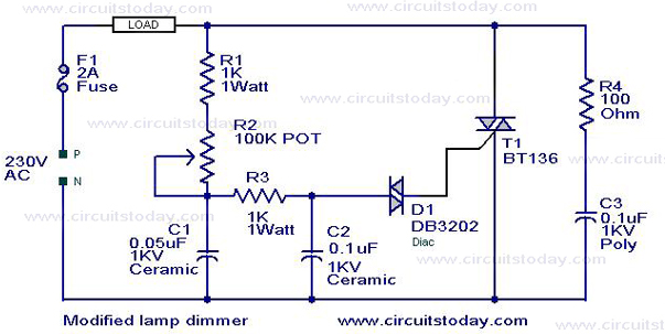
This is a modification of the Simple Lamp Dimmer/Fan Regulator circuit that was previously posted. The operation of the circuit remains the same as the original; however, it now includes a snubber circuit composed of resistor R4 and capacitor...
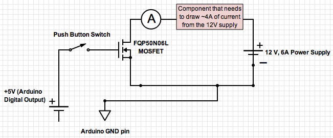
If the ground of the Arduino is disconnected from the negative terminal of the power supply, current flows through the MOSFET, even when the switch is not closed. In an electronic circuit involving an Arduino and a MOSFET, maintaining a...
Due to the varying conditions of different input signals, when an abnormal voltage is applied to the pin, protection circuits are designed to create a circuit path that secures the internal protection of large-scale integration (LSI) circuits. The structure...

A simple instrumentation amplifier circuit diagram utilizing an operational amplifier (op-amp). The equation for gain, along with design, working principles, and construction details, are also provided. An instrumentation amplifier is a type of differential amplifier that has been designed to...
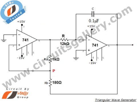
An operational amplifier-based triangular waveform generator is a simple circuit that is widely used in function generators. This circuit utilizes the 741 operational amplifier to create a triangular wave generator. The output waveform of an integrator will be triangular...