
Light Dimmer Circuit TRIAC dimmer circuitCircuitWorking
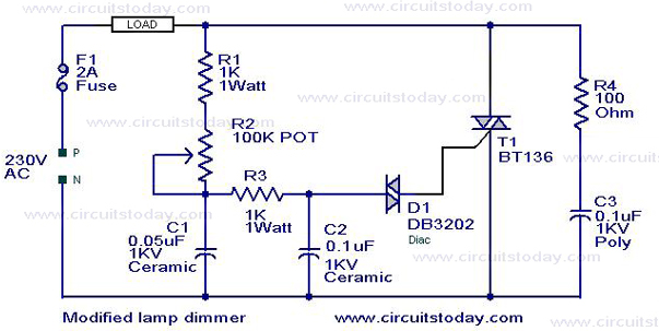
The modified circuit retains the fundamental operation of the original lamp dimmer and fan regulator design, allowing for variable control of the load. The addition of the snubber circuit serves a crucial role in managing voltage transients that can occur during the switching operations of the triac. The resistor R4 and capacitor C3 work together to suppress high-frequency noise and prevent voltage spikes, thereby enhancing the reliability and longevity of the triac T1.
The inclusion of a fuse in the circuit design is a significant safety feature. It provides overcurrent protection, ensuring that in the event of a fault or overload, the circuit will be interrupted, preventing potential damage to the components and reducing the risk of fire hazards. The selection of an appropriately rated fuse is essential to ensure that it operates effectively without nuisance tripping during normal operation.
Overall, this modified circuit presents a robust solution for controlling lamps and fans, integrating safety and performance improvements that enhance its practical application in various settings. Proper component selection and layout are critical to achieving optimal performance and safety standards in the final implementation of this circuit.This is a modification of the circuit Simple Lamp Dimmer/Fan Regulator previously posted here. The working of the circuit is same as that of the previous, but in addition a snubber circuit consisting of resistor R4 and capacitor C3 is included to improve the performance of the triac T1. A fuse is also included for better safety. I think this is t he better circuit to try. 🔗 External reference
Related Circuits

A TTL hex inverter circuit can function as a DC/DC converter, converting 5V to 12V. This circuit encompasses all necessary functionalities for DC/DC conversion. It relies on a TTL switching threshold voltage regulator. The components U1A and U1B form...

A reliable full bridge driver is essential for driving a flyback transformer. While many flyback driver schematics exist, most lack durability. The well-known Zero Voltage Switching (ZVS) driver, invented by Vladmiro Mazilli, is recognized for its reliability due to...
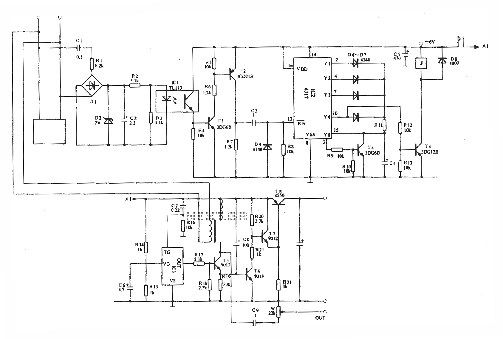
Optically isolated phone automatic recording interface circuit, IC3 voice module. The optically isolated phone automatic recording interface circuit is designed to capture audio signals from a telephone line while ensuring electrical isolation between the phone line and the recording device....
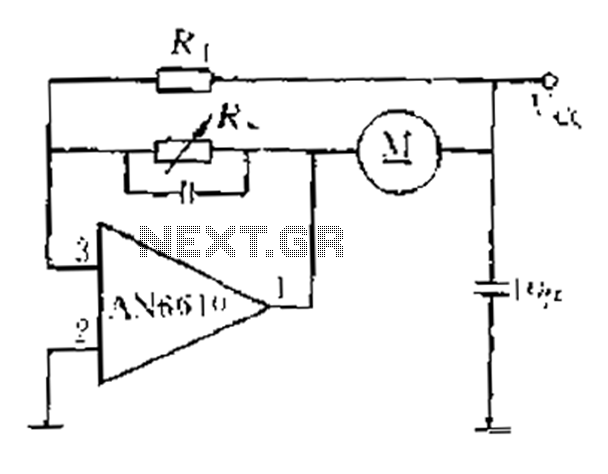
AN6610 Application Circuit operates as follows: When the supply voltage (Vcc) changes due to mechanical load variations, it can affect the motor speed. The motor speed is proportional to the back electromotive force (EMF). Consequently, the voltage across the...
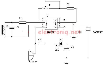
A simple metal detector electronic project circuit can be designed using the CS209A integrated circuit manufactured by Cherry Semiconductor. The CS209A integrated circuit is a bipolar monolithic integrated circuit intended for metal detection and proximity sensing applications. It incorporates...
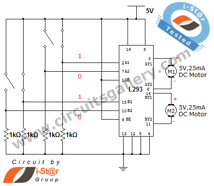
How can a DC motor be rotated in clockwise and counterclockwise directions? This is a common question posed by many robotics beginners. DC motor driver circuits are essential components in robotics workshops. The L293D IC is frequently utilized for...
Warning: include(partials/cookie-banner.php): Failed to open stream: Permission denied in /var/www/html/nextgr/view-circuit.php on line 713
Warning: include(): Failed opening 'partials/cookie-banner.php' for inclusion (include_path='.:/usr/share/php') in /var/www/html/nextgr/view-circuit.php on line 713