
How To Build A Simple Car Alarm And Immobilizer
This circuit serves as a comprehensive vehicle security system that integrates various functionalities to enhance the safety and protection of the vehicle. The automatic exit and entry delays are designed to provide users sufficient time to secure their vehicle without triggering the alarm inadvertently. The switching mechanism, relying on Cmos technology, ensures efficient operation with minimal power consumption. The inclusion of an optional instant alarm zone adds another layer of security, allowing users to monitor additional areas of the vehicle, such as the trunk or hood, which are often vulnerable to unauthorized access.
The use of external relays for immobilization and light activation is a strategic feature that enhances the deterrent effect of the alarm system. By wiring the relay to activate with the ignition, the system ensures that the alarm is armed whenever the vehicle is turned off, establishing a robust security protocol. The design accommodates various configurations, allowing for customization based on user preferences and vehicle specifications.
The alarm's sound output can be tailored to suit user needs, with the option for intermittent or continuous siren sounds, providing flexibility in alerting the owner or deterring potential intruders. The time delays for exit and entry are adjustable, offering users the ability to fine-tune the system to their specific requirements.
The circuit's reliance on existing vehicle infrastructure, such as door switches, simplifies installation while maintaining functionality. The design also considers the need for additional switches, ensuring that users can expand the system to cover more areas without compromising performance.
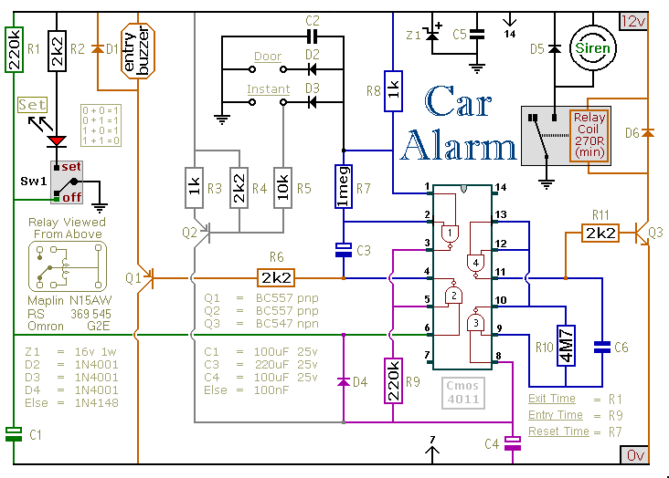
Overall, this vehicle security circuit represents a well-thought-out solution for enhancing vehicle safety, combining user-friendliness with effective security measures. Proper installation and adherence to safety guidelines will ensure reliable operation and long-term functionality of the system.This circuit features automatic exit and entry delays - an optional instant alarm zone - an optional intermittent siren output - and an automatic reset. By adding external relays you can immobilize the vehicle and flash the lights. For automatic operation - use the contacts of a small relay in place of Sw1. Wire the relay coil so that it`s energiz ed while the ignition is on. Then - every time you turn the ignition off - the alarm will set itself. Once Sw1 is opened you have about 10 to 15 seconds to get out of the vehicle and close the door behind you. When you return and open the door the buzzer will sound. You have 10 to 15 seconds to move Sw1 to the off position. If you fail to do so - the siren will sound. The output to the siren is intermittent. That is - it switches on and off. The speed at which it switches on and off is set by C6 & R10. If you want a constant siren output - leave out C6 & R10 - and connect pins 8 & 9 of the Cmos 4011 together.
One of the alarm`s inputs is connected to the vehicle`s existing door-switches. This provides the necessary exit and entry delays. It`s usually sufficient to connect a single wire to just one of the door switches. These switches are generally all connected in parallel - with the return through the chassis. You can add extra normally-open switches to the door-circuit if you wish - but note that any additional switches will have to be able to carry the current required by your vehicle`s interior light. Any number of normally-open switches may be connected - in parallel - to the "Instant" input. Since they don`t have to carry the current for the interior light - you can use any type of switch you like.
You may want an instant alarm on the bonnet - the boot - the rear-hatch - the rear-doors etc. It doesn`t matter if these already have switches connected to the door-circuit. Simply fit a second switch and connect it to the instant input. It will override the delay circuit. You can use the chassis for the return. However, a ground terminal is provided if - for any reason - you need to run a separate return wire for either zone. The exit delay is set by R1 & C1 - the entry delay by R9 & C4 - and the reset time by R7 & C3. The precise length of any time period depends on the characteristics of the actual components used - especially the tolerance of the capacitors and the exact switching points of the Cmos gates.
However - for this type of application - really accurate time periods are unnecessary. While any trigger-switch remains closed - the siren will continue to sound. About 2 to 3 minutes after all of the switches have been opened - the alarm will reset. The circuit is designed to use an electronic Siren drawing 300 to 400mA. It`s not usually a good idea to use the vehicle`s own Horn - because it can be easily located and disconnected. However - if you choose to use the Horn - remember that the alarm relay is too small to carry the necessary current.
Connect the coil of a suitably rated relay to the "Siren" output. This can then be used to sound the Horn - flash the lights etc. The Support Material for this circuit includes a step-by-step guide to the construction of the circuit board, a parts list, a detailed circuit description and more. The circuit board and switches must be protected from the elements. Dampness or condensation will cause malfunction. Fit a 1-amp in-line fuse AS CLOSE AS POSSIBLE to your power source. This is VERY IMPORTANT. The fuse is there to protect the wiring - not the alarm. Exactly how the system is fitted will depend on the make of your particular vehicle. Consequently, I CANNOT give any further advice on installation. Before fitting this or any other immobilizer to your vehicle - carefully consider both the safety implications of its possible failure - and the legal consequences of installing a device that could cause an accident.
If you decide to proceed - you`ll need to use the highest sta 🔗 External reference
Related Circuits
A project involving a moisture sensor alarm circuit designed to detect moisture levels in plant soil, wood, and irrigation areas. The moisture sensor alarm circuit typically consists of a moisture sensor, a microcontroller or comparator circuit, an alarm system, and...
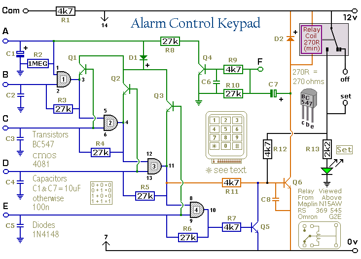
This keypad is designed for use with the Modular Burglar Alarm system, although it can be applied in various other contexts. Inputting the first four digits of a selected five-digit code will activate the relay, while entering the complete...
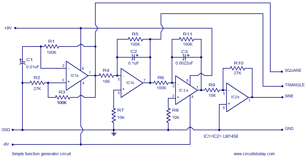
A simple function generator circuit utilizing the LM1458 is presented here. The LM1458 is a dual general-purpose operational amplifier. The two op-amps within the LM1458 share a common bias network and power supply line, yet operate independently. The function generator...

An amplifier is a device that increases the voltage in a circuit. The simplest type is an operational amplifier, and this video will demonstrate how these devices function and how to implement them in electronic applications. As an example,...

555 Timer with Audio Alarm Circuit. This circuit serves as a straightforward electronic timer equipped with an audio alarm feature. The 555 timer is a versatile integrated circuit widely used in various timer, delay, pulse generation, and oscillator applications. In...
Sal, thank you for the response. If the plugs could be acquired and the signals transmitted to the PC using the software you are utilizing... The circuit design involves the integration of plugs that can be connected to a signal...