
Wide Band O2 and data logger for 84-89 Carrera
The circuit design involves the integration of plugs that can be connected to a signal source, allowing for the transmission of data to a personal computer (PC). The primary components of this schematic include the plugs, signal conditioning circuitry, and a communication interface to the PC.
The plugs serve as the input interface where the signals are captured. These plugs can be of various types depending on the nature of the signals, such as audio, digital, or analog. The selection of plugs should match the signal characteristics to ensure accurate data acquisition.
Once the signals are captured, they are fed into signal conditioning circuitry. This circuitry may consist of amplifiers, filters, and analog-to-digital converters (ADCs) to prepare the signals for processing. Amplifiers boost the signal strength for better clarity, while filters eliminate unwanted noise that could interfere with the data. The ADC converts the analog signals into digital format, making them compatible with the PC.
The communication interface, which could be USB, serial, or wireless, facilitates the transfer of the conditioned signals to the PC. The software running on the PC processes the incoming data, allowing for analysis, visualization, or further manipulation of the signals.
Overall, this schematic outlines a system designed for efficient signal acquisition and processing, ensuring that the data collected is accurate and readily usable for various applications.Originally Posted by CliffBrown Sal Thanks for the reply. If the plugs could be purchased and the signals fed to the PC with the software you`re using .. 🔗 External reference
Related Circuits
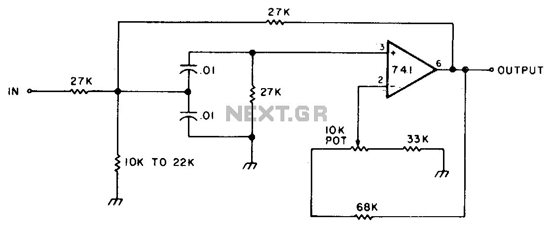
This circuit features adjustable bandwidth with a center frequency of approximately 800 Hz. A 10 kΩ potentiometer is used to adjust the bandwidth, varying from approximately ±350 Hz to ±140 Hz at the 3 dB down points. The circuit operates...
This section discusses Compact Flash, Flash-ATA, and hard disks. For additional media, refer to DATA LOGGING TO RAM CARDS on page 274 and DATA LOGGING TO FLASH AND RAM CHIPS on page 279. This module enables the rapid creation...
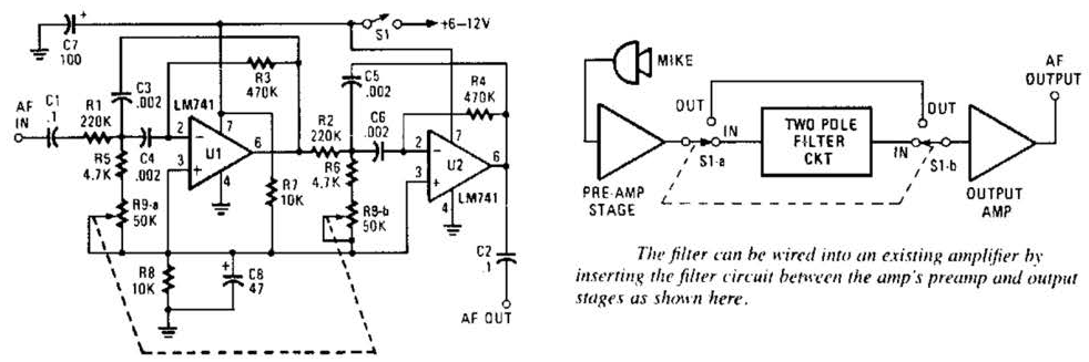
This variable-frequency audio bandpass filter is constructed using two 741 operational amplifiers connected in cascade. The two 741 op amps are configured as identical RC active filters and are cascaded to enhance selectivity. The filter's tuning range spans from...
This application note details the operation and features of the FAN7601, a BCDMOS programmable frequency current mode PWM controller designed for offline adapter applications and auxiliary power supplies. To minimize power loss during light and no-load conditions, the FAN7601...
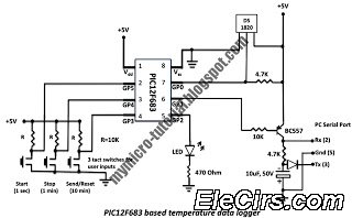
A data logger is a device that records measurements over time. The measurements could be any physical variable like temperature, pressure, voltage, humidity, etc. This project describes how to build a mini logger that records surrounding temperature. A data logger...
The MSF transmitter transmits time data bit-by-bit over 60 seconds each minute by modulating a 60 kHz carrier frequency. It employs a continuous wave (CW) signal. Two bits are sent every second through variations in the duration and number...