
how to build a simple led light chaser circuit
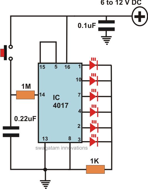
The schematic for the LED running lights features the CMOS 4017 decade counter, which is designed to sequentially activate a series of LEDs in a chaser pattern. The 4017 IC operates by counting clock pulses generated by the 4049 oscillator, which serves as a square wave generator. This oscillator can be configured to produce a desired frequency, thus controlling the speed of the LED sequence.
In the circuit, the output pins of the 4017 are connected to individual LEDs, which are typically arranged in a linear or circular pattern for visual effect. Each output pin corresponds to a specific LED, turning it on in succession as the counter increments. The circuit can be enhanced with resistors to limit current through the LEDs, ensuring they operate within safe limits.
The design may also include a capacitor connected to the oscillator to stabilize the frequency and improve performance. A power supply, typically 9V or 12V, is required to power the circuit, and appropriate bypass capacitors should be placed near the ICs to filter out noise and stabilize operation.
The schematic should also include a brief explanation of how to set up the components on a breadboard or PCB, along with any necessary connections for the power supply and ground. With careful assembly, this circuit can effectively create an eye-catching display of running lights suitable for various applications, such as automotive lighting or decorative displays.Want to make a set of attention-getting LED running lights? This article provides a circuit diagram and discussion of the CMOS logic and IC layout for a simple sequential LED flasher or light chaser that one can build, including the parts lists. The heart of the project is the CMOS 4017 Logic IC paired to an IC 4049 oscillator.. 🔗 External reference
Related Circuits
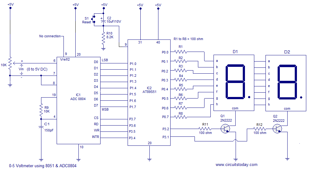
A simple 0-5 digital voltmeter utilizing the 8051 (AT89S51 microcontroller) is presented, accompanied by a circuit diagram and assembly language (ASM) code. This digital voltmeter is designed for straightforward voltage measurement. The circuit employs an AT89S51 microcontroller, which serves as...

The application circuit operates the device as illustrated below. It is designed for cooling electrical equipment, typically utilizing a cooling fan to dissipate heat. The LCE employs a synchronous control socket on the device and its connections remain unchanged....

This power supply is designed for the Modular Burglar Alarm but is suitable for various applications. It delivers a 12-volt output with a maximum current of 1 amp. In case of a mains failure, the backup battery activates immediately,...
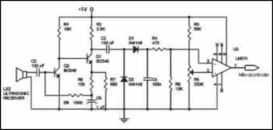
Ultrasonic receivers detect an ultrasonic signal emitted by an ultrasonic transmitter at a specific frequency. The received signal is filtered using a band-pass filter circuit that allows only the predetermined frequency range to pass. The output signal is then...
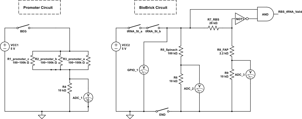
The kit employs an off-the-shelf microcontroller based on the AtMega328P-PU Arduino, along with a simplified version designed for ease of replication and modification by collaborators and students. This initiative aims to enable the fabrication of simplified microcontrollers for DIY...
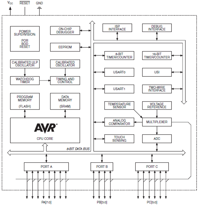
The ATtiny1634 8-Bit AVR Microcontroller from Atmel is based on the enhanced RISC architecture of AVR. It can execute powerful instructions in a single clock cycle, achieving throughputs close to 1 MIPS per MHz. This allows system designers to...