
Ultrasonic Wave Receiver Circuit Schematic Diagram
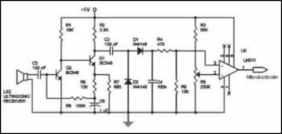
The ultrasonic receiver circuit operates by first capturing ultrasonic waves emitted by a transmitter. The ultrasonic transmitter generates sound waves at a specific frequency, which are then detected by the ultrasonic receiver. The received signal undergoes filtering through a band-pass filter, specifically designed to allow frequencies within a certain range to pass while attenuating others. This filtering process is crucial to ensure that only relevant signals are processed, reducing noise and improving accuracy.
Following the filtering stage, the filtered signal is amplified to a suitable level for further processing. The amplifier increases the signal strength, making it easier for the comparator to discern between high and low logic states. The comparator circuit plays a vital role in determining the proximity of the ultrasonic source. It compares the amplified signal to a predetermined reference voltage. This reference voltage is set based on the expected output of the amplifier when the sensor is at a specific distance from an obstacle, such as a wall.
The output of the comparator indicates whether the detected distance is within the acceptable range for the intended operation (e.g., turning direction). If the detected distance is less than or equal to the minimum threshold, the comparator outputs a high signal (logic '1'). Conversely, if the distance exceeds this threshold, the output is low (logic '0'). This binary output is then transmitted to a microcontroller, which interprets the signal and calculates the distance based on the timing of the received ultrasonic waves.
The microcontroller processes this information to make decisions or trigger actions based on the proximity of objects detected by the ultrasonic receiver. This functionality is essential in applications such as obstacle avoidance in robotic systems or automated parking assistance in vehicles. The integration of these components—ultrasonic transmitter, receiver, band-pass filter, amplifier, comparator, and microcontroller—creates a cohesive system capable of accurately measuring distances and facilitating responsive actions based on those measurements.Ultrasonic recipients will receive an ultrasonic signal emitted by an ultrasonic transmitter in accordance with the characteristic frequency. Received signal is going through the process of filtering using the frequency band pass filter circuit, with a frequency value that is passed has been determined.
Then the output signal will be amplified and passed to the comparator circuit (comparator) with a reference voltage determined based on the amplifier output voltage when the distance between the sensor mini vehicles with bulkhead / retaining walls to reach the minimum distance for the turn direction. Comparator output can be considered under these conditions is high (logic `1 `), while longer distances are low (logica`0`).
Binary logics are then forwarded to the circuit controller (microcontroller). So when there is an ultrasonic signal into the circuit, then the comparator will issue a logic low (0V), which will then be processed by the microcontroller to calculate the distance. You are reading the Circuits of Ultrasonic Wave Receiver Circuit And this circuit permalink url it is
🔗 External reference
Related Circuits
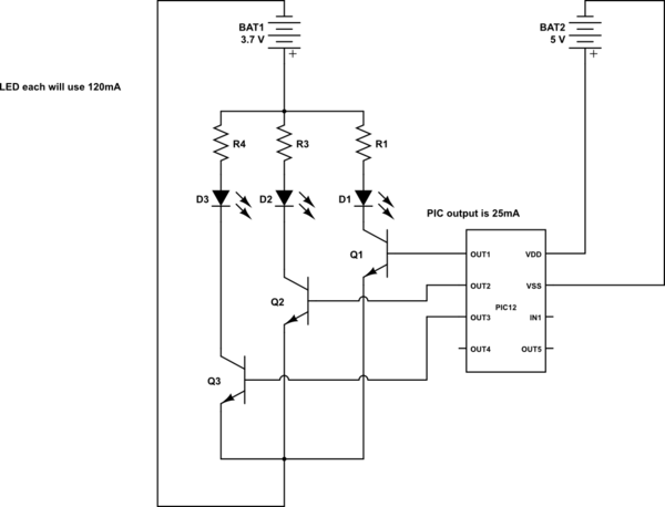
This is a conceptual schema utilizing a PIC12 microcontroller to control the blinking of three LEDs, each exhibiting different blinking patterns. There are several questions that need to be addressed. The circuit design involves a PIC12 microcontroller, which is a...
In addition to its primary function as a headphone amplifier, this circuit is applicable in various scenarios requiring a wide bandwidth low power amplifier. It utilizes an operational amplifier (op-amp) with its output current enhanced by a pair of...

This simple circuit consists of a transformer, two diodes, a capacitor, and an ammeter. To charge a battery, connect the positive and negative terminals of the circuit to the corresponding terminals of the battery. When the battery is not...
Most peripherals that interface with a PC utilize a USB port. The computer's power supply circuit, specifically the switched-mode power supply (SMPS), is designed to provide constant power to all internal components. However, when external peripherals that require a...
Almost all DC amplifier circuits are utilized as the input stage of differential circuits. Many complementary symmetry circuits also employ a double differential complementary sub-circuit along with a constant current source for the input stage. The constant current source...
The Electronic Cash Register (ECR) keeps track of sales transactions quickly and effectively. An abundance of PLUs (Price Look Ups) and department keys accommodate a variety of merchandise items. This means a faster, more accurate check out process and...