
Digital voltmeter using 8051 microcontroller AT89S51 with circuit diagram and software

The circuit employs an AT89S51 microcontroller, which serves as the core processing unit. The input voltage range is from 0 to 5 volts, making it suitable for various low-voltage applications. The microcontroller interfaces with an Analog-to-Digital Converter (ADC), which converts the analog voltage signal into a digital format that the microcontroller can process.
In the schematic, the ADC is connected to one of the microcontroller's input pins. The microcontroller reads the digital value from the ADC and processes it to display the corresponding voltage on a 7-segment display or an LCD. The use of a resistor divider may be necessary if the input voltage exceeds the 5V limit, ensuring the voltage remains within the ADC's operational range.
The assembly language code is responsible for initializing the microcontroller, configuring the ADC, reading the digital output, and managing the display output. The code includes routines for converting the ADC value into a voltage representation and controlling the display to show the measured voltage.
This design highlights the integration of microcontroller technology with basic electronic components to create an efficient and effective digital voltmeter suitable for educational purposes or simple measurement tasks.Simple 0-5 digital voltmeter using 8051 (AT89S51 microcontroller) with circuit diagram and assembly language ASM code. Simple digital voltmeter.. 🔗 External reference
Related Circuits
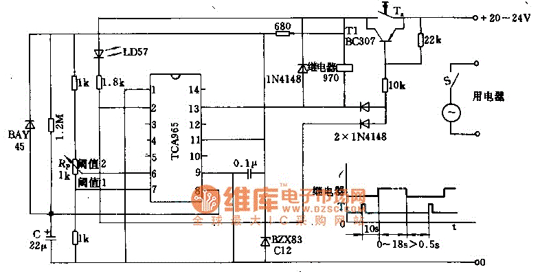
The foot 13 between valve value 1 and valve value 2 will draw the transistor base current. If the relay releases, after a recovery time of 0.5 seconds, pressing the key will initiate the switching process again. The timer...
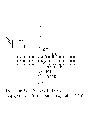
This circuit is a simple IR detector for testing IR remote controllers. The circuit is based on one phototransistor which receives the IR beam. The NPN transistor works as an amplifier which feeds current to the LED. When this...
An LCD (liquid crystal display) is an electronically modulated optical device composed of multiple pixels filled with liquid crystals, arranged in front of a light source (backlight) or reflector to create images in color or monochrome. The block diagram...
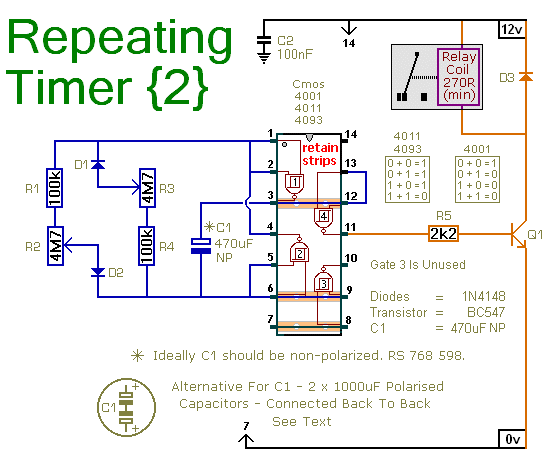
This circuit is based on a simple asymmetric oscillator. The duration for which the relay remains energized and the duration for which it remains de-energized are independently set. With the component values indicated in the diagram, both durations are...
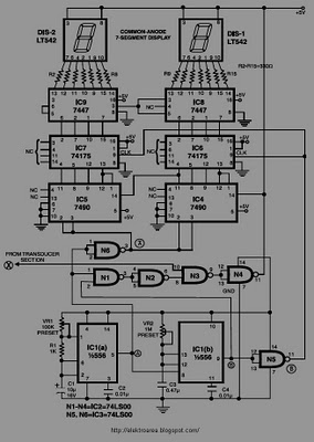
This circuit is designed to display the speed of a vehicle in kilometers per hour (km/h). An opaque disc is mounted on the spindle connected to the front wheel of the vehicle. The disc features evenly spaced holes along...

This method can be illustrated using an uncommon semiconductor power flip-flop. A flip-flop is a toggling circuit with two stable states (bistable multivibrator) that retains its output state without an input pulse. Triacs can be used to implement flip-flops...