
How to build a zener diode tester

The zener diode testing circuit operates by utilizing a transformer to step down the 120V AC line voltage to a more manageable level suitable for testing. The circuit typically includes a rectifier stage, which converts the AC voltage to DC, allowing for accurate measurement of the zener diode's breakdown voltage.
In this configuration, a variable resistor or potentiometer may be included to adjust the current flowing through the zener diode, ensuring that it operates within its specified limits. A multimeter can be connected across the zener diode to measure the voltage drop, confirming whether the diode is functioning correctly.
Safety precautions must be taken when working with high voltages; therefore, the circuit should include fuses and proper insulation to prevent accidental contact with live components. Additionally, the circuit may incorporate LED indicators to provide visual feedback on the status of the zener diode under test, enhancing usability and safety during operation.
Overall, this testing circuit is essential for verifying the performance of zener diodes in various applications, ensuring their reliability in voltage regulation and protection circuits.This is a circuit to test zener diodes. It hooks up to a 120V AC line and boosts the output .. 🔗 External reference
Related Circuits
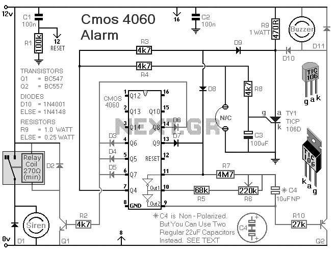
This is a single-zone alarm system equipped with automatic exit, entry, and siren cut-off timers. It can accommodate various types of normally-closed input devices, such as magnetic reed contacts, foil tape, and passive infrared sensors (PIRs). Additionally, it is...
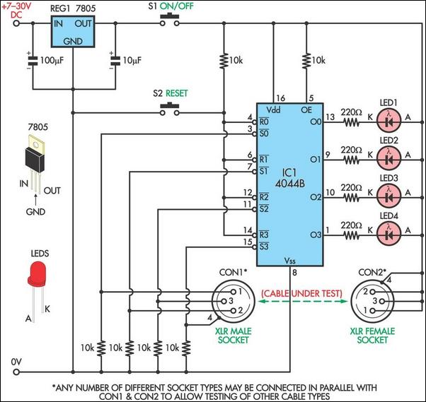
This circuit is designed to facilitate the testing of microphone cables or other types of cables for intermittent breaks that are often challenging to detect with a multimeter. The circuit can accommodate cables with up to four cores. It...
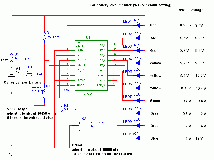
This circuit utilizes the widely available LM3914 integrated circuit (IC), which is straightforward to operate and does not require external voltage regulators due to its built-in voltage regulation capabilities. It can be powered from various sources. When the test...
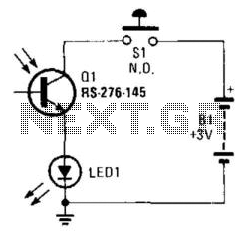
Using a battery, a phototransistor, and a visible-light LED, this simple circuit functions as a "go/no go" tester for infrared remote control devices. The illumination of the LED indicates that the phototransistor is being modulated by infrared energy. This circuit...
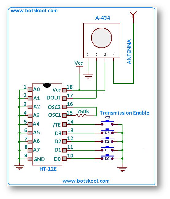
The simplest approach to creating a remote-controlled robot is to repurpose a low-cost wireless toy car by removing its receiver module and remote control. Alternatively, one can design a custom RF remote using an ASK (Amplitude Shift Keying) based...
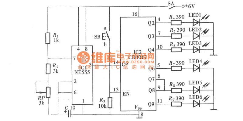
The Reaction Capability Tester is utilized to assess and enhance an individual's quick-response abilities. It features various designs, with the depicted model comprising a CD4017 decimal counter and a light-emitting diode (LED). The construction of the Reaction Capability Tester...