
Infrared Remote Control Tester
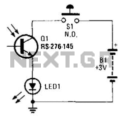
This circuit operates on the principle of light modulation, where the infrared (IR) signal from a remote control is detected by the phototransistor. The circuit consists of a power source, typically a battery, which provides the necessary voltage for operation. The phototransistor is sensitive to infrared light, allowing it to detect signals emitted by IR remote controls.
When the remote control is activated, it emits an IR signal that is received by the phototransistor. This signal causes the phototransistor to conduct, allowing current to flow through the circuit. The flow of current is then used to illuminate a visible-light LED. The LED serves as an indicator, visually confirming that the phototransistor is receiving IR energy and that the remote control is functioning correctly.
The circuit's simplicity makes it an effective tool for testing the functionality of IR remote controls. It can be easily assembled on a breadboard or a printed circuit board (PCB) using basic electronic components. The design can also be enhanced by incorporating additional features, such as adjustable sensitivity or a more sophisticated LED indicator system, to provide more detailed feedback on the strength of the received signal. Overall, this circuit is a practical application in the field of electronics, particularly for troubleshooting and testing IR remote devices. Using a battery, a phototransistor and a visible-light LED, this simple circuit is a " "go/no go"" tester fo r IR remote control devices. The illumination of the LED indicates that Ql is being modulated by IR energy. 🔗 External reference
Related Circuits
This is an infrared gate with two sensors planned to use in the wall in the way behind a door. It can be applied in a toilet to keep track of that someone is inside exceeding a certain amount...
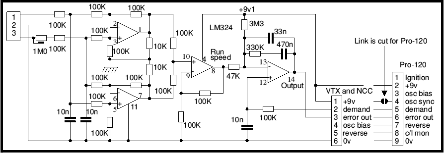
Most battery motor speed controllers are under manual control and the operator automatically adjusts speed to match demand. Under these conditions closed loop motor speed control is an unnecessary expense. However, when it is required, a tachogenerator can easily...
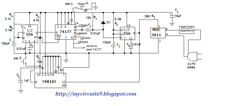
This document presents an electronic project focused on device control using a timer. This circuit allows for the activation of an appliance at a specified time for a predetermined duration. It can be applied to manage the operation of...

This 555 timer circuit is a remote control jammer device that is useful for blocking the use of remote controls, particularly when children frequently change channels or settings. The 555 timer is a versatile integrated circuit that can be configured...
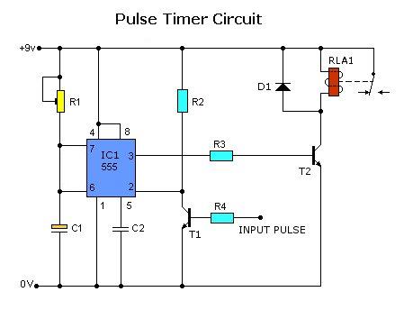
Today, solutions are offered for a timed control relay that utilizes Normally Open (NO) and Normally Closed (NC) contacts to manage the operation of other devices, enabling or disabling them as needed. The functionality of this circuit is based...
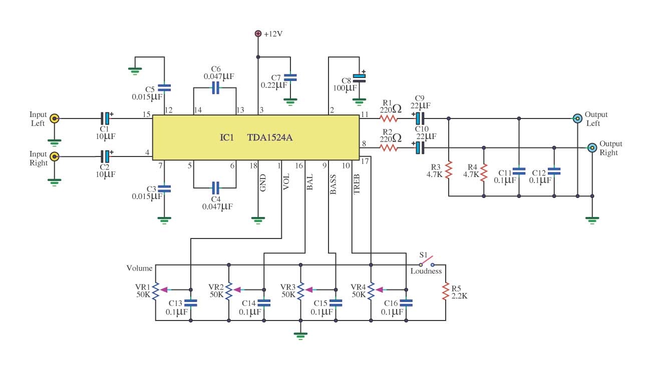
This is a simple tone control circuit using the TDA1524A, which is a key component in this IC chip diagram from Philips. The circuit allows for tone control adjustments such as bass, treble, and balance, enabling users to fine-tune...