
How To Build A Burglar Alarm Using A Cmos 4060
The single-zone alarm system is designed to provide a reliable security solution for various applications. The system's architecture includes a microcontroller or logic circuit that manages the timing sequences for exit and entry delays, ensuring user-friendly operation. The integration of normally-closed input devices allows for seamless connectivity with existing security infrastructure, while the option to add normally-open triggers enhances flexibility in deployment.
The exit and entry delay mechanisms are critical for user convenience, allowing individuals to enter and exit without inadvertently triggering the alarm. The adjustable settings via resistor R6 enable customization based on user preference or specific security needs, accommodating different environments.
The siren's activation protocol, which includes a single sound upon entry delay expiration, serves to deter intruders while minimizing disruption to occupants. The extended siren cut-off period ensures that any potential intrusions are adequately addressed without immediate cessation of alert signals.
In terms of component selection, the choice of a relay compatible with the voltage supply is essential for the system's overall functionality. The circuit's design anticipates various power supply scenarios, providing versatility across different installations.
The use of polarized capacitors arranged in a non-polarized configuration illustrates a practical engineering solution, ensuring the oscillator's reliable operation. This clever workaround is particularly beneficial in scenarios where non-polarized capacitors are scarce, emphasizing the importance of adaptability in electronic design.
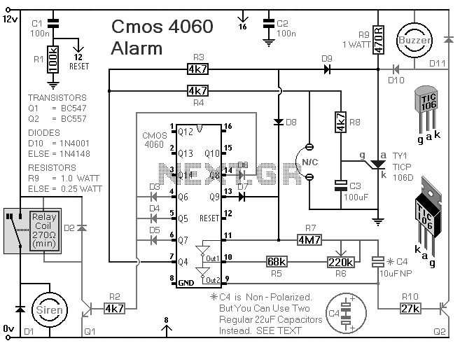
Overall, the single-zone alarm system represents a robust solution for security applications, combining ease of use, flexibility in configuration, and reliable performance through thoughtful component selection and circuit design.This is a single zone alarm - with automatic exit, entry and siren cut-off timers. It will accommodate all the usual types of normally-closed input devices - such as magnetic-reed contacts - foil tape - PIRs etc. But it`s easy to add a normally-open trigger. I`ve used a 12-volt supply in the drawing - but the circuit will work at anything from 5 t o 15-volts. All you need do is select a siren, buzzer, and relay to suit the voltage you`re using. When you switch the alarm on - the buzzer will sound eight times. This is the exit delay. Before the end of the eighth beep - you can leave the building without activating the alarm. R6 controls the length and speed of the beeps. It can be adjusted to give an exit delay of anything from about ten seconds - up to about a minute. After the eighth beep - the buzzer should stop sounding. This confirms that the loop has been restored within the time allowed. If the buzzer does not stop - but changes instead to a continuous beep - the loop is open and the building isn`t secure. When this happens - you should switch off the alarm - and check for open doors, windows etc. When you return and open the door - the buzzer will sound again - and the entry delay will start. The entry delay is the same length as the exit delay. But to distinguish it from the exit delay - the buzzer will sound continuously. If the buzzer is sounding continuously - the alarm has been activated - and the entry delay has begun.
If you don`t switch the alarm off before the entry delay expires - the siren will sound. The siren will sound only once. Just as R6 sets the lengths of the exit and entry delays - it also sets the siren cut-off time. The siren cut-off delay is 30 times the length of the exit delay. With the exit delay set at 30-seconds - the siren will sound for about 15-minutes. Then it will switch off - and remain off. After the cut-off timer has switched the siren off - the buzzer will continue to sound. So when you return - if the buzzer is sounding - you`ll know that the alarm has been activated. Note that D10 is optional. Its job is to sound the buzzer constantly during the entry delay. It`s also responsible for keeping the buzzer going after the siren has stopped. If you leave out D10 - the buzzer will beep eight times during both the exit and entry delays. And - when the siren cuts-off - the buzzer will cut off also. A regular electrolytic capacitor is polarised. If the charge on its plates is the wrong way round - DC current will flow through the capacitor. If the current is high enough - the capacitor will heat up and explode. The presence of R5 in the circuit means that this is not going to happen. But if you use a polarised capacitor - it may mean that the oscillator won`t run - or won`t run reliably. While the oscillator is running - the polarity of the charge on C4 keeps reversing. So C4 needs to be non-polarised. However - you can simulate a non-polarised 10uF capacitor by connecting two 22uF polarised capacitors back to back - as shown.
How and why this works is explained in the Detailed Circuit Because non-polarised capacitors aren`t widely available - the prototype was built using two polarised capacitors. 🔗 External reference
Related Circuits
Below are a couple circuits you can use to produce a 32.768 KHz square wave from a common watch crystal. The output can be fed to a 15 stage binary counter to obtain a 1 second square wave. The...
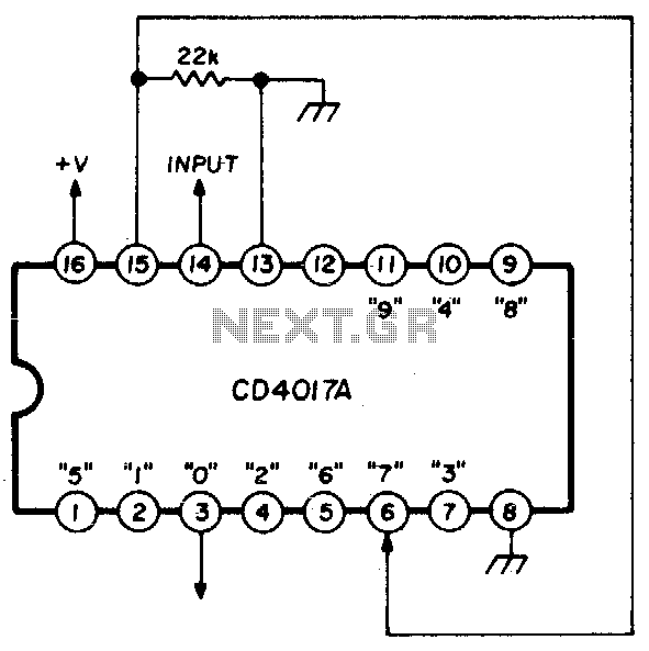
A single connection change allows division by any integer between 2 and 10. The RCA CD4017A Johnson decade counter is configured as a divide-by-7 counter. A resistor is utilized to maintain the reset line in a low state. When...
This LED (Light Emitting Diode) display consists of 10 LEDs to indicate the level of an input signal. If the signal is low, only LED #1 will light up. As the signal level increases, the illuminated dot will progress...

In the event of a sudden power failure in an elevator, it is crucial for the duty officer in the distribution room to be alerted promptly to prevent panic among passengers trapped inside. The following describes a sound alarm...
This beeper circuit utilizes two 555 integrated circuits (ICs) and can operate within a supply voltage range of 5 to 15V DC. It is suitable for applications requiring an alarm or beeping signal. The first IC (IC1) is configured...
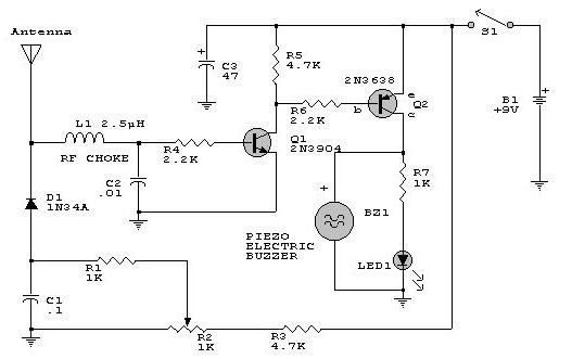
This electronic RF detector project is designed using common transistors and a few standard electronic components. The RF detector responds to RF signals below the standard broadcast band and well over 500 MHz, providing both visual and audible indications...
Warning: include(partials/cookie-banner.php): Failed to open stream: Permission denied in /var/www/html/nextgr/view-circuit.php on line 713
Warning: include(): Failed opening 'partials/cookie-banner.php' for inclusion (include_path='.:/usr/share/php') in /var/www/html/nextgr/view-circuit.php on line 713