
how to get more power out of a astable multivibrator

To successfully integrate a DPDT relay into the circuit, it is essential to consider the relay's activation requirements and the circuit's design. The relay coil must match the voltage supplied by the power source. For a 6V relay to function correctly, the circuit must ensure that the voltage across the relay coil is maintained at 6V when activated. If the relay does not activate, check the following:
1. **Coil Resistance**: Measure the resistance of the relay coil. If it is too high, the current may be insufficient to energize the relay. Ensure that the circuit can provide the necessary current for the relay.
2. **Transistor Driver**: If the circuit uses a transistor to control the relay, verify that the transistor is properly biased. The base current must be sufficient to saturate the transistor, allowing maximum current to flow through the relay coil.
3. **Diode Protection**: Include a flyback diode across the relay coil to protect the circuit from voltage spikes generated when the relay is deactivated. This diode should be oriented to allow current to flow in reverse only when the relay is switched off.
4. **Power Supply**: When using a 12V battery, the circuit's components must be rated to handle the higher voltage. If the circuit remains continuously active, inspect the triggering mechanism. Ensure that the control signal correctly turns off the relay when desired. This may involve adding a pull-down resistor to stabilize the input signal or adjusting the control logic.
5. **Capacitance Values**: The 100µF capacitors may need to be adjusted based on the relay's operating characteristics, as the timing and response of the circuit can be affected by changes in capacitance. Experimenting with different capacitance values may yield better results.
By addressing these key areas, the integration of the DPDT relay into the circuit should be achievable, enabling the desired functionality while maintaining stable operation with both 6V and 12V power sources.Powering this circuit with a 6v alkaline battery, the circuit works just fine with 100uf capacitors. But the problem is I want to replace the LED with a dpdt relay, I tried a 6v one I had laying around but it wont budge. Also when I tried the circuit with a 12v battery, the circuit just remains active for all the time. How do I get this to work 🔗 External reference
Related Circuits
This simple circuit indicates the amount of power delivered to a loudspeaker. The dual-color LED displays green at an applied power level of approximately 1 watt. At 1.5 watts, it glows orange, and above 3 watts, it shines bright...
This is a straightforward, cost-effective Hi-Fi quality power amplifier. It can be constructed in five different configurations, as indicated in the table, ranging from 20 W to 80 W RMS. This Hi-Fi quality power amplifier is designed to deliver high...
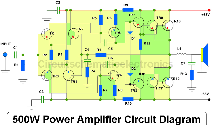
This amplifier has an output power of approximately 500 Watts, with a compatible voltage supply of up to 63 Volts. When operating, the output transistors should be mounted on an adequate heatsink due to the significant heat generated during...
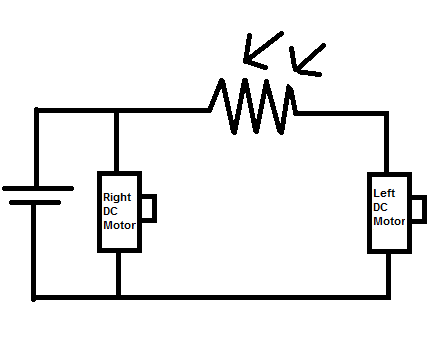
Construct a toy device that spins to the left whenever there is an obstruction in front of it, without utilizing a microcontroller. The proposed design involves using two DC motors as the rear wheels. An LDR (Light Dependent Resistor)...
My FM Wireless Microphone has been a very popular project with beginners and experienced constructors alike. It has been used inside guitars and as the basis of a remote control system. I do however, receive many requests for a...
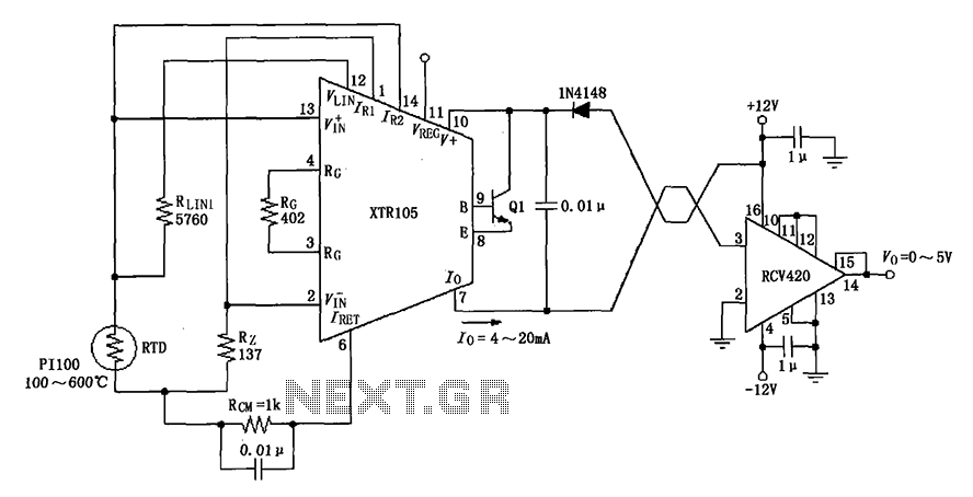
The circuit utilizes a Pt100 type resistance temperature detector (RTD). It operates within a temperature range of 100 to 600 °C, where the XTR105 outputs a current of 4 to 20 mA, and the RCV420 provides an output voltage...