
XTR105 RCV420 composed of 12V power transmission reception circuit diagram of the ring

The described circuit employs a Pt100 RTD, which is a type of temperature sensor that provides a resistance of 100 ohms at 0 °C. As the temperature increases, the resistance of the RTD correspondingly increases, allowing for precise temperature measurements. The XTR105 is a current output signal conditioning device that converts the resistance change of the RTD into a proportional current output. The specified output range of 4 to 20 mA is standard for industrial applications, allowing for easy integration into control systems and providing a robust signal that is less susceptible to noise over long distances.
The RCV420 is utilized to convert the current signal from the XTR105 into a voltage output, specifically ranging from 0 to 5 V. This voltage output can be easily interfaced with various data acquisition systems or controllers, facilitating real-time monitoring and control of temperature.
The schematic indicates a two-wire configuration for the RTD connection, which is common in many applications. However, for remote sensing applications, a three-wire configuration is recommended to compensate for lead resistance, which can introduce measurement errors. In this setup, RG is specified as 383 ohms, and RLIN2 is set to 8060 ohms, which are likely used for balancing the circuit and ensuring accurate readings by minimizing the impact of lead resistance.
Overall, this circuit design is aimed at providing accurate temperature measurements in a wide range of industrial applications, ensuring reliable performance and ease of integration into existing systems. As shown in FIG, RTD using Pt100 type thermocouple. When the temperature is 100 ~ 600oC when, XTR105 output current 4 ~ 20mA, RCV420 output voltage of 0 ~ 5V. The figure for th e two-wire RTD connection, if for remote RTD, recommends a three-wire RTDs connected, RG is 383, RLIN2 to 8060 .
Related Circuits

This easy-to-construct handy pen torch electronic circuit has a low component count and utilizes two power white LEDs for illumination. A low voltage (4.8V DC) supply is derived from a built-in rechargeable Ni-Cd battery pack and is converted into...
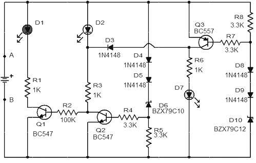
When the battery voltage is 11.5V or less, transistor Q1 is activated, and LED D1 will illuminate. When the battery voltage is between 11.5V and 13.5V, transistor Q2 is activated, causing LED D2 to light up. At a battery...

This FM spy telephone circuit is connected in series with the phone line. When there is a signal on the wires, this transmitter will radiate airwaves through the wires. This FM spy telephone circuit operates by integrating with the existing...
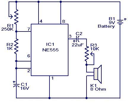
This weblog focuses on electronic circuit schematics, PCB design, DIY kits, and diagrams for electronic projects. A simple circuit utilizing the NE555 IC is presented, which can be employed to generate metronomes. This circuit is particularly beneficial for music...

A micro mixer circuit is designed to be simple, affordable, compact, and versatile. This circuit can mix up to four input channels, including microphone signals, FM tuners, AUX, and other signals, as illustrated in Figure 1. The operation begins...
This sound frequency meter circuit is simple to build and can be constructed in a portable format. It can measure frequencies with a minimum level of 10 mV. The sound frequency meter circuit is designed to provide an effective and...