
How to interface LEDs with 8051 Microcontroller

The 8051 microcontroller is a widely used embedded system component known for its versatility and ease of use in various applications. In this setup, the P2 port is utilized for output, where multiple LEDs can be connected. Each LED can be controlled individually or in groups, depending on the logic implemented in the microcontroller's firmware. The P1 port, designated for input, is connected to six switches that allow user interaction.
When a switch connected to the P1 port is pressed, it sends a signal to the microcontroller, which can then process this input. The microcontroller's program can be designed to respond to each switch in a unique way, resulting in different LED patterns. For example, pressing switch one might cause a specific LED to turn on, while pressing switch two could lead to a different LED illuminating or a combination of LEDs flashing in a sequence.
To implement this circuit, it is essential to configure the microcontroller's I/O ports correctly. The P2 port should be set as an output port, while the P1 port is configured as an input port. Pull-up resistors may be used on the switches to ensure that the input reads a high state when the switch is not pressed. When the switch is pressed, the input state changes to low, allowing the microcontroller to detect the switch activation.
In summary, this basic operation of the 8051 microcontroller with LEDs and switches serves as an excellent introduction for beginners. It illustrates fundamental concepts such as digital input and output, user interaction, and simple programming logic, providing a solid foundation for further exploration and experimentation with microcontroller applications.This post is related to basic operation of 8051 microcontroller with LEDs. LEDs are connected with P2 port & 6 switches are connected with P1 port of 8051. By pressing different switches, LEDs will glow in different manners. This post may be very helpful for 8051 microcontroller beginners. 🔗 External reference
Related Circuits
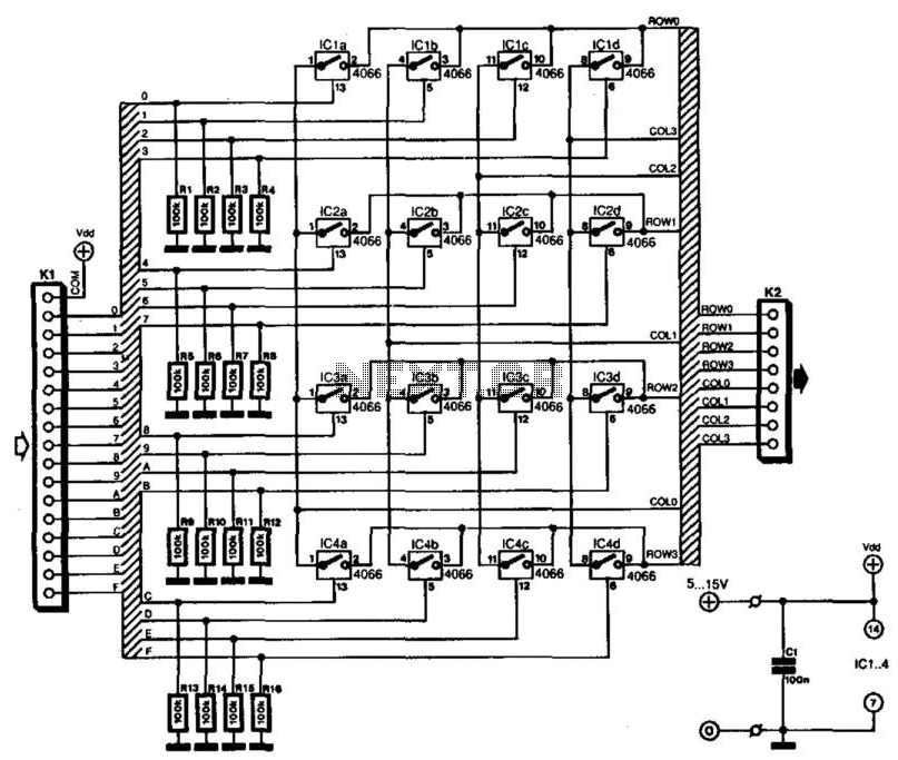
Keyboards can be classified into two categories based on the connection method of the switches: those with a common connection and those arranged in a matrix. The matrix type offers the significant advantage of minimizing the number of connections,...
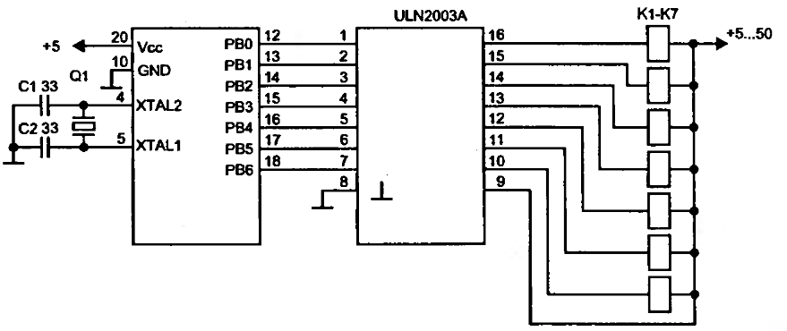
To drive a relay, a current greater than 20mA is required, which cannot be supplied by a single microcontroller pin. Therefore, a relay cannot be connected directly to a microcontroller pin. Instead, a simple amplifier circuit consisting of a...

Nowadays, every institution requires automation. As part of college automation, a project has been developed titled "Voice Interactive System for College Automation." This project enables users to quickly access student attendance and marks through a telephone line without the...

NOTE: There is no guarantee as to the suitability of said circuits and information for any purpose whatsoever other than as a self-training aid. I.E. If it blows your equipments, trashes your hard disc, wipes your backup, burns your...
Using a switch to power up your microcontroller projects may not be a good idea if you need to "wake" the PIC during some events. For example: A metal detector sends a pulse indicating a car is ready to...
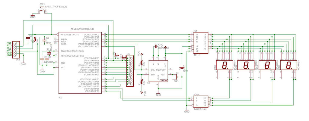
This is the second instructable focused on creating a digital watch as a learning experience. An Atmega644 chip from a Sanguino was available, which would have sufficed, but the intention was to burn an Arduino bootloader and test its...