
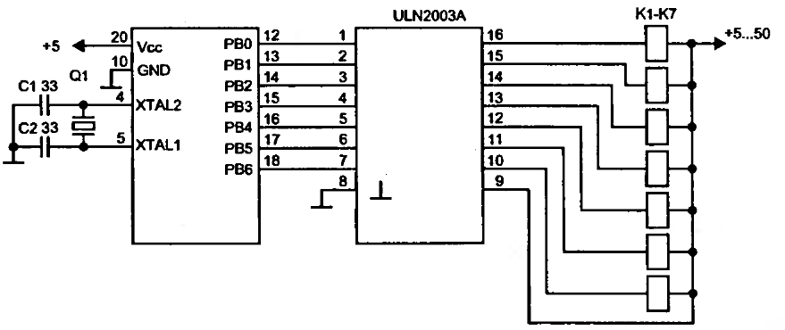
Drive relay with AVR microcontroller
To implement a relay driver circuit using a transistor, the following components and configuration are typically utilized. The basic arrangement consists of a microcontroller, a transistor (such as a NPN type), a relay, a diode, and a resistor.
1. **Microcontroller**: The microcontroller outputs a low current signal (typically 5V) to control the transistor. This signal is connected to the base of the transistor through a current-limiting resistor, which is usually in the range of 1kΩ to 10kΩ.
2. **Transistor**: The NPN transistor acts as a switch. When the microcontroller sends a high signal to the base, the transistor turns on, allowing current to flow from the collector to the emitter. This current is sufficient to energize the relay coil.
3. **Relay**: The relay is connected between the collector of the transistor and a power supply. When the transistor is activated, the relay coil is energized, closing the relay contacts and allowing current to flow to the load (lamp, motor, etc.).
4. **Diode**: A flyback diode is placed in parallel with the relay coil, oriented to allow current to flow in the reverse direction when the relay is de-energized. This protects the transistor from voltage spikes generated by the inductive load of the relay.
5. **Integrated Circuits**: For controlling multiple relays, using ICs like the ULN2003 or ULN2803 is advantageous. These chips contain multiple Darlington pairs, enabling them to drive several loads simultaneously. Each output can handle up to 500mA, making them suitable for larger applications.
This configuration allows for safe and efficient control of relays and other inductive loads, ensuring that the microcontroller operates within its current limits while effectively managing higher power devices.To drive relay you need more than 20mA the current can one pin drive. This is why you cannot connect relay directly to microcontrollers pin. To drive relay you need to connect simple amplifier made of one transistor. This circuit is more general as instead relay you can connect any other load like lamps, DC motors if you need to control more t han one relay, you might consider using ICs like ULN2003 or ULN2803. These ICs haveDarlingtontransistors inside and can drive up to 500mA each. We aim to transmit more information by carrying articles. Please send us an E-mail to wanghuali@hqew. net within 15 days if we are involved in the problems of article content, copyright or other problems. We will delete it soon. 🔗 External reference
Related Circuits
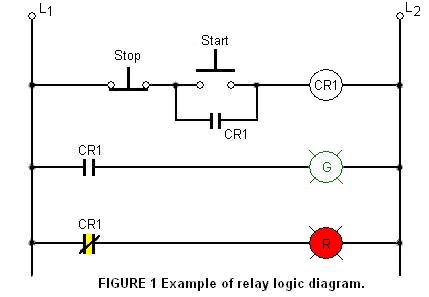
The relay logic circuit creates an electrical schematic diagram for controlling input and output devices. Components include resistors, capacitors, and others. The relay logic circuit operates by utilizing electromechanical relays to control various input and output devices in a systematic...
The circuit is not particularly susceptible to motor transients and supports FULL STEPS FORWARD, FULL STEPS REVERSE, ACTIVE HOLD, and POWER OFF aka RELEASED. If the motor does not turn then swap around the leads of ONE of the...

This circuit utilizes a 4049 integrated circuit (IC) to control a 2N2222 switching transistor. The transistor, in turn, drives a piezo transducer known as crystal 1. The circuit design begins with the 4049 IC, which is a hex inverter capable...
Balanced signals consist of two lines that have opposite phases and should be received with a differential input receiver. Balanced signals are employed in many applications. Balanced signals are primarily used in audio and communication systems to minimize noise and interference....
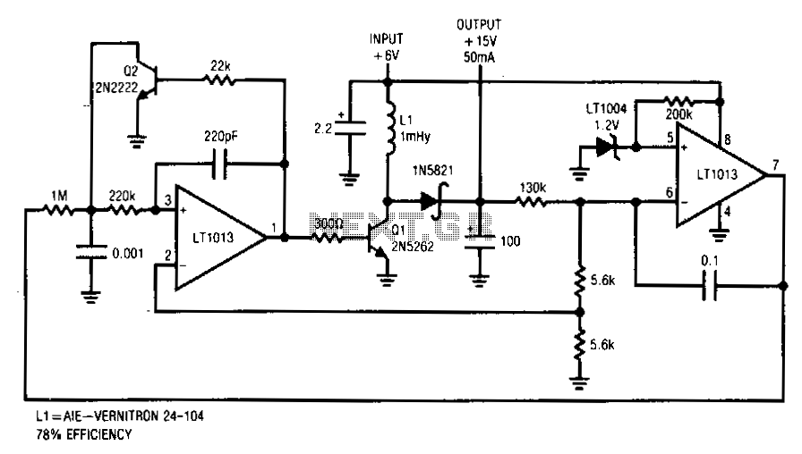
This converter delivers up to 50 mA from a 6-V battery with 78% efficiency. This flyback converter functions by feedback-controlling the frequency of inductive flyback events. The inductor's output is rectified and filtered to de-bias the feedback loop to...
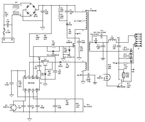
A high brightness LED evaluation board has been developed using the Fairchild Semiconductor FAN7554D PWM controller. The evaluation board for high brightness LEDs incorporates the Fairchild Semiconductor FAN7554D PWM controller, which is designed to provide efficient power management and precise...