
Arduino 7 segment Displays Digital Clock With Charlieplexing LEDs
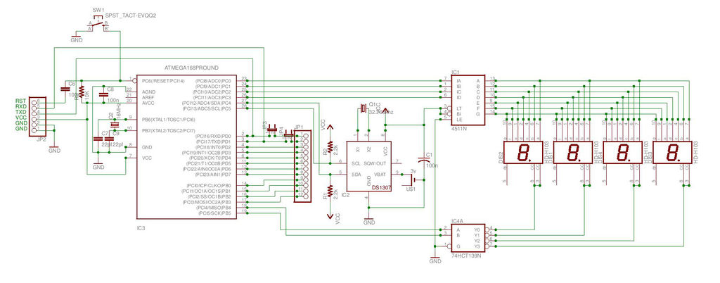
The digital watch circuit utilizes an Atmega168 microcontroller to drive four seven-segment displays configured in a common cathode arrangement, interfacing with the 4511 BCD to 7-segment latch/decoder/driver and the 74HC139 dual 2-to-4 line decoder/demultiplexer. The DS1307 real-time clock (RTC) module communicates with the Atmega168 via I2C, ensuring accurate timekeeping and the ability to retain time settings during power loss through a backup battery. The circuit design incorporates pull-up resistors on the I2C lines to ensure reliable communication.
The schematic includes connections for the seven-segment displays, with appropriate current-limiting resistors to prevent excessive current draw. The use of jumpers in the Express PCB file is specified to accommodate the single-sided design, allowing for manual wire connections where necessary. The design emphasizes the importance of disconnecting the LEDs from the RX and TX pins during programming to prevent interference, highlighting a practical consideration for circuit design and microcontroller programming.
The final layout can be produced either by printing the Express PCB file onto copper-clad material or by utilizing the Eagle schematic to create a professionally manufactured PCB. This project serves as a comprehensive example of integrating various components in a digital watch application, demonstrating both the challenges and learning opportunities in electronics design and programming.This is my second instructable. I just had a mood of making a digital watch. But wanted to make it a learning process. I already had a sanguino i could have easily used that Atmega644 chip. it would have been more than enough. But i wanted to try burning a Arduino bootloader and see if i could make it work. Well i did. I used a Atmega168 for this project. I used 4 seven segment displays to display time in 24hr format. Here ii experimented with common anode and common cathode. Now i wanted to use other chips too and not just the Arduino which would have been the easier option. The chips i experimented with are 74LS47, 74HC154, 74HC595, 4511 and 74HC139. The final compatible combination was common cathode with 4511 and 74HC139. I used a RTC chip DS1307 to feed the time to the Arduino. I initially wanted to use millis() function in Arduino but it is not that accurate. Using RTC not only saved long coding but also has an added advantage of keeping the time in case the external supply is cutoff.
It uses a 3v battery to do this. I have made the circuit in Eagle but sadly I am not thatproficientin using the software (Which is next on my TO LEARN list) so I didn`t make the board. I have attached the schematic i made on Eagle. U can use it to make the board. I used Express PCB to create the PCB. I have also attached this. pcb file here. You can eitherprint this file directly and make a pcb from a copper clad or build a board from Eagle and get it made professionally.
1) In express PCB fileI`veused JMP at some places. It means you have to use wires to short the two pads. This was necessary since i used a single sided PCB. Confirm where to connect wires from the circuit diagram. 2) At digital pin 0 and 1 i have used jumpers. This is VERY IMPORTANTas the LEDS have to bedisconnectedfrom these points as they are RX and TX pins. LEDs if connected while uploading the program will use up the voltage and hinder the uploading. I learnt it the hard way. So i made changes afterwards. So while uloading Remove the jumpers thus effectively disconnecting them from LEDs and replace them once the uploading is done.
🔗 External reference
Related Circuits

The latest circuit diagram of the AD2496 is presented here. All modifications intended and described in the article regarding the prototype have been implemented. Additionally, two current-compensated chokes have been introduced to enhance electromagnetic compatibility (EMC) immunity. While these...
Upon entering the password, the application, in this case "LED," will illuminate. In this digital locking system project, the interfacing of a keypad and a 16x2 LCD with a microcontroller will be explored, along with the accompanying code. This...
This is a very simple to implement Temperature Sensor. It uses LM35DT as a semiconductor temperature sensor which operates with a +5 volt DC. It produces an analog output voltage, proportional to the change in surrounding temperature in Celsius...
A simple digital circuit is presented that can be used to precisely control the AC power supply. This circuit does not include a digital-to-analog conversion component. In its application, effective control is established through a computer system that sends...
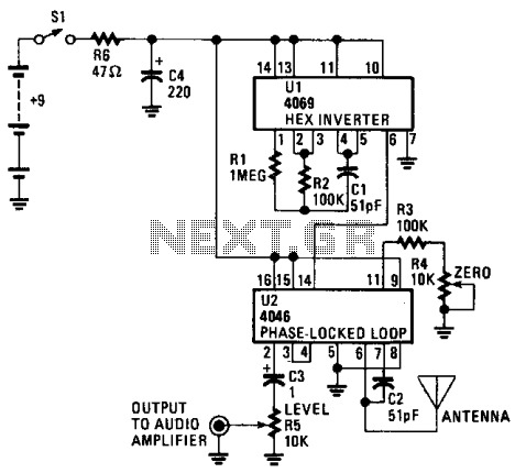
The CD4069 or 74C04 hex inverter is utilized as a fixed-frequency oscillator centered around 100 kHz. U2 includes the variable frequency oscillator and balanced modulator. The CD4046 functions as a phase-locked loop, with R3, R4, and C2 determining the...
The diagram illustrates a block diagram for an agenda alarm and agenda thermometer system. It includes one temperature sensor, a real-time clock (RTC), a microcontroller (PIC), an EEPROM, a 7-segment display, and a keyboard. The EEPROM is utilized to...