
How to make a PC-Micro controller USART communication using AVR-Atmega8
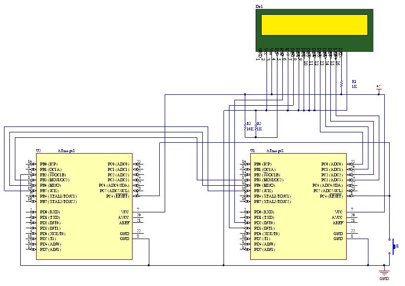
To establish communication between a PC and an AVR Atmega8 microcontroller using the USART (Universal Synchronous and Asynchronous serial Receiver and Transmitter) module, several key components and steps must be considered. The USART module allows for serial communication, which is essential for data transmission in embedded systems.
The connection is typically made through the RS232 protocol, which defines the electrical characteristics and timing of the signals. The PC's COM port serves as the interface for the RS232 communication. It is important to ensure that the voltage levels are compatible between the PC and the microcontroller. The RS232 standard uses voltage levels of -12V to +12V, while the Atmega8 operates at TTL levels (0V to 5V). Therefore, a level shifter or RS232 to TTL converter is necessary to bridge this gap.
The AVR Atmega8 microcontroller features a built-in UART, which can be configured for asynchronous communication. The microcontroller's USART can be set up to match the baud rate of the PC's COM port to ensure proper data transmission. Common baud rates include 9600, 19200, and 115200 bps, among others.
To implement the communication, the following steps should be followed:
1. **Hardware Setup**: Connect the RX (Receive) pin of the Atmega8 to the TX (Transmit) pin of the RS232 converter, and the TX pin of the Atmega8 to the RX pin of the RS232 converter. Ensure that the ground of the microcontroller and the PC are connected together to establish a common reference.
2. **Software Configuration**: In the Atmega8 firmware, initialize the USART by setting the baud rate, enabling the transmitter and receiver, and configuring the frame format (data bits, stop bits, and parity). This can be accomplished using the appropriate registers such as UBRRH, UBRRL, UCSRB, and UCSRC.
3. **Data Transmission**: Use the USART transmit and receive functions to send and receive data. The data can be sent as characters or bytes, and the microcontroller can be programmed to respond to incoming data accordingly.
4. **Error Handling**: Implement error checking mechanisms, such as parity bits or checksums, to ensure data integrity during transmission.
5. **Testing**: After setting up the hardware and software, conduct tests to verify that data can be successfully sent and received between the PC and the Atmega8 microcontroller. Use terminal software on the PC to facilitate communication and monitor the data exchange.
By following these guidelines, effective data communication can be established between a PC and an AVR Atmega8 microcontroller using the USART module, enabling a wide range of applications in embedded systems.How to transmit data between PC and AVR Atmega8 micro controller using USART module. We use COM port of PC based on RS232 protocol & UART of AVR.. 🔗 External reference
Related Circuits
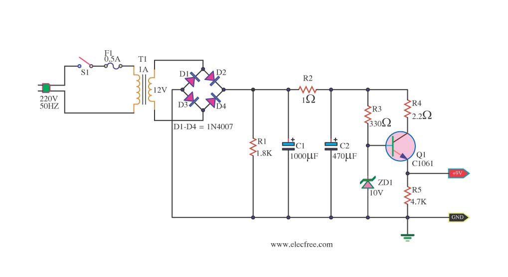
This is a DC power supply circuit designed to regulate 9 volts and provide a current output ranging from 1 amp to 2 amps. The circuit utilizes a modified TIP31 transistor, although alternative transistors such as TIP41, MJE3055, or...
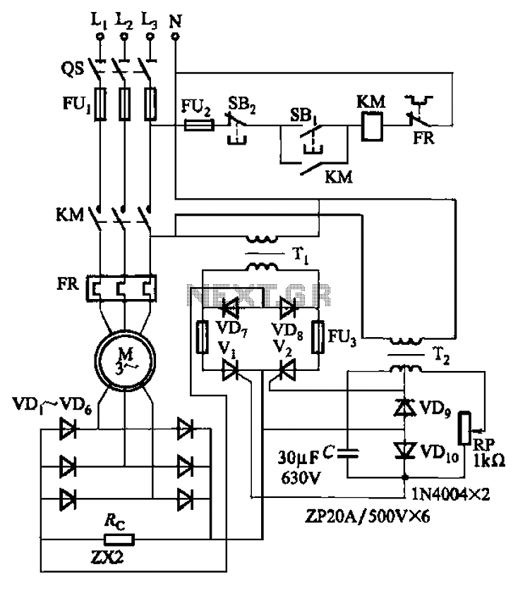
The circuit depicted in Figure 3-171 includes an auxiliary power supply that operates on single-phase AC power. It features a single-phase half-wave controlled bridge composed of diodes VD7, VD8, and thyristors V1, V2. The output current is managed by...
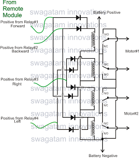
The market is filled with high-end remote-controlled toy cars; however, for hobbyists, creating one at home can be a unique experience. The following article explains how to configure a simple remote-controlled toy car using a pre-made 4-relay remote control...

This is the design circuit diagram of an ultrasonic mosquito repeller. The circuit operates based on the theory that insects, such as mosquitoes, can be repelled by sound frequencies in the ultrasonic range (above 20 kHz). The circuit utilizes...
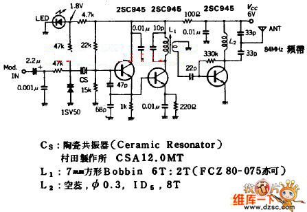
The quartz crystal oscillator circuit is highly advantageous in terms of frequency stability. Even the Voltage-Controlled Crystal Oscillator (VCXO) circuit, which allows for significant frequency changes, typically experiences only about a 1% variation. However, the linear range of control...
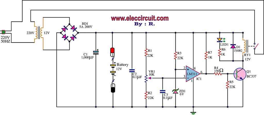
The best 12 Volt battery charger circuit is an automatic system that activates when the battery voltage falls below a specified threshold. This 12 Volt battery charger circuit is designed to efficiently charge lead-acid batteries while ensuring safety and longevity....
Warning: include(partials/cookie-banner.php): Failed to open stream: Permission denied in /var/www/html/nextgr/view-circuit.php on line 713
Warning: include(): Failed opening 'partials/cookie-banner.php' for inclusion (include_path='.:/usr/share/php') in /var/www/html/nextgr/view-circuit.php on line 713