
Make a Remote Controlled Toy Car Circuit
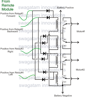
The configuration of the remote-controlled toy car involves integrating a 4-relay remote control module, which serves as the central component for controlling the car's movements. Each relay corresponds to a specific function, allowing for discrete control of various actions such as forward, backward, left, and right movements. The remote control module typically operates at a frequency that ensures reliable communication between the remote handset and the receiver unit installed in the car.
To begin the assembly, the user must first wire the relay module according to the provided schematic. The relays are connected to the motor driver circuit, which interfaces with the DC motors responsible for propelling the vehicle. The power supply for the entire system should be carefully selected to match the voltage and current ratings of both the motors and the relay module, ensuring efficient operation without overloading any components.
The remote control handset is equipped with four buttons, each linked to a specific relay. When a button is pressed, the corresponding relay is activated, allowing current to flow to the associated motor or function. This setup enables precise control of the toy car's direction and speed, making it an engaging project for hobbyists.
While the article emphasizes the circuit and wiring, the physical construction of the toy car body requires creativity and engineering skills. The user is encouraged to design a lightweight chassis that accommodates the motors, relay module, and power supply. Materials such as plastic, wood, or metal can be utilized, depending on the desired durability and aesthetics of the final product.
In conclusion, this project not only provides a practical application of electronics and remote control technology but also fosters creativity and hands-on skills in designing and building a functional remote-controlled toy car.The market may be full of these hi-end remote controlled toy cars, but for a hobbyists making one at home can be entirely a different experience. The article belowexplainshow to configure a simple remote controlled toy car using a ready made 4-relay remote control module.
If you refer one of the previous articles you will find some data regarding buying of ready made, ready to use remote control modules or devices, which just requires to be wired as per the data and you are able to control any electrical device within a range of 100 meters with a press of a button over the remote handset. In this article only the circuit and the wiring part has been discussed, making the car body and fitting of the motors and the wheels will be entirely left on the user, the user may take the help of a carpenter or some fabricator for designing the vehicle body.
The remote control module which is being discussed here uses four discrete relays, which can be toggleed discreretly through the 4 individual switches over the remote handset. 🔗 External reference
Related Circuits
Instructions to assemble a small project on wireless energy transfer. If anyone has a simple schematic suitable for beginners, please share or provide instructions. The simplest one found so far is from a Hungarian YouTube channel, but it is...
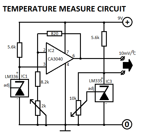
This circuit is designed for Fahrenheit measurements, with the freezing point set at 320°F. At 2120°F, P2 is adjusted to achieve an output voltage of 0.9V. The circuit operates by utilizing a temperature sensor that converts temperature readings into a...
The internal disconnection circuit for a blanket operates on the principle of induction. It includes a wire approximately 2 cm in length that senses the proximity of a charged mains power source. When the sensing wire is close to...
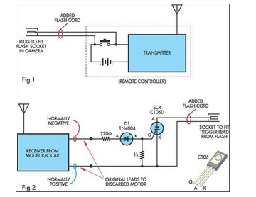
A radio-controlled electronic flash is an essential tool in any photographer's kit. Professionals frequently utilize them, such as wedding photographers. A radio-controlled electronic flash system typically consists of a transmitter and one or more receivers. The transmitter, often mounted on the...
The battery charger circuit is designed to charge 6V 4.5 AH lead-acid batteries. The schematic is straightforward and utilizes only a few components. The IC LM317T serves as the core component of the circuit. It features an automatic charging...
The following circuit illustrates a Video and DVD Modulator in a VHF/UHF electronic diagram. Features include an oscillator that utilizes a transistor for high-frequency operation. The video and DVD modulator circuit serves to convert video signals into a format suitable...