
how to make digital voltmeter

The digital voltmeter circuit utilizes the ICL7107 integrated circuit, which is specifically designed for digital voltmeter applications. The ICL7107 converts the analog voltage input into a digital output that can be displayed on a 3.5-digit LED display. The LED display is configured to show voltages up to 199.9V, with the capability of indicating negative voltages through its display functionality.
Powering the circuit with a regulated 5V supply ensures stable operation, while the low current consumption of approximately 25mA makes it suitable for battery-operated applications. The compact design of the printed circuit board (PCB) measuring 3cm x 7cm allows for easy integration into various electronic projects or devices.
To enhance the visibility of the LED display, the brightness can be tailored by manipulating the number of 1N4148 diodes in series with the display segments. This flexibility enables users to optimize the display for different lighting conditions. The inclusion of a 220-ohm resistor connected to pin 4 of the LED display is critical for limiting the current and protecting the display from potential damage.
The versatility of the voltmeter is further enhanced by its ability to measure different voltage ranges. By substituting the existing 1M ohm resistor with a 100K ohm resistor, the circuit can accurately measure lower voltages, specifically from 0 to 19.99V, with an impressive resolution of 0.01V. This feature makes the voltmeter suitable for applications requiring precise voltage measurements, such as in laboratory settings or for troubleshooting electronic circuits.This digital voltmeter is ideal to use for measuring the output voltage of your DC power supply. It includes a 3. 5-digit LED display with a negative voltage indicator. It measures DC voltages from 0 to 199. 9V with a resolution of 0. 1V. The voltmeter is based on single ICL7107 chip and may be fitted on a small 3cm x 7cm printed circuit board. The c ircuit should be supplied with a 5V voltage supply and consumes only around 25mA. Brightness of the LED display segments can be varied by adding or removing 1N4148 small signal diodes that are connected in series. Use two 1N4148 diodes for higher LED display brightness. 220 Ohm resistor should be connected to the PIN 4 on the first LED display. The voltmeter can also be configured to measure different voltage ranges and display higher voltage resolution.
Replacing 1M with 100K resistor will allow to measure 0 - 19. 99V voltages with 0. 01V (10mV) accuracy. 🔗 External reference
Related Circuits
Redesign a complex solution using minimal external components, resulting in a low-cost application that provides high-precision measurements. This digital thermometer microcontroller project utilizes a watchdog timer function to measure temperature. The watchdog timer (WDT) on all PIC microcontrollers has...
Unlike most surface-mounted device (SMD) resistors, SMD ceramic capacitors do not have their values marked. To determine the value of these capacitors, a capacitance meter is required. SMD ceramic capacitors are widely used in modern electronic circuits due to their...
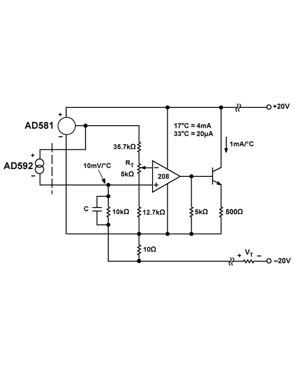
The AD592 is a two-terminal monolithic integrated circuit temperature transducer that produces an output current proportional to absolute temperature. It functions as a high-impedance temperature-dependent current source of 1 µA/K across a wide range of supply voltages. Enhanced design...
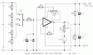
The MOSFET input of the CA3140 is ideally suited for use in a high impedance DC voltmeter. The range selector is controlled by switch S1. The input impedance is limited to 10M by the resistors in the voltage divider,...
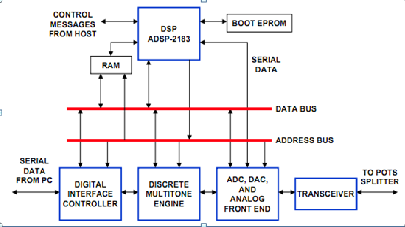
DSP Applications in ADSL (Asymmetric Digital Subscriber Line) can be explored further in Microsoft Office Word. The widespread popularity of the World Wide Web has led to unprecedented levels of Internet traffic. A recent study by the Wall Street...
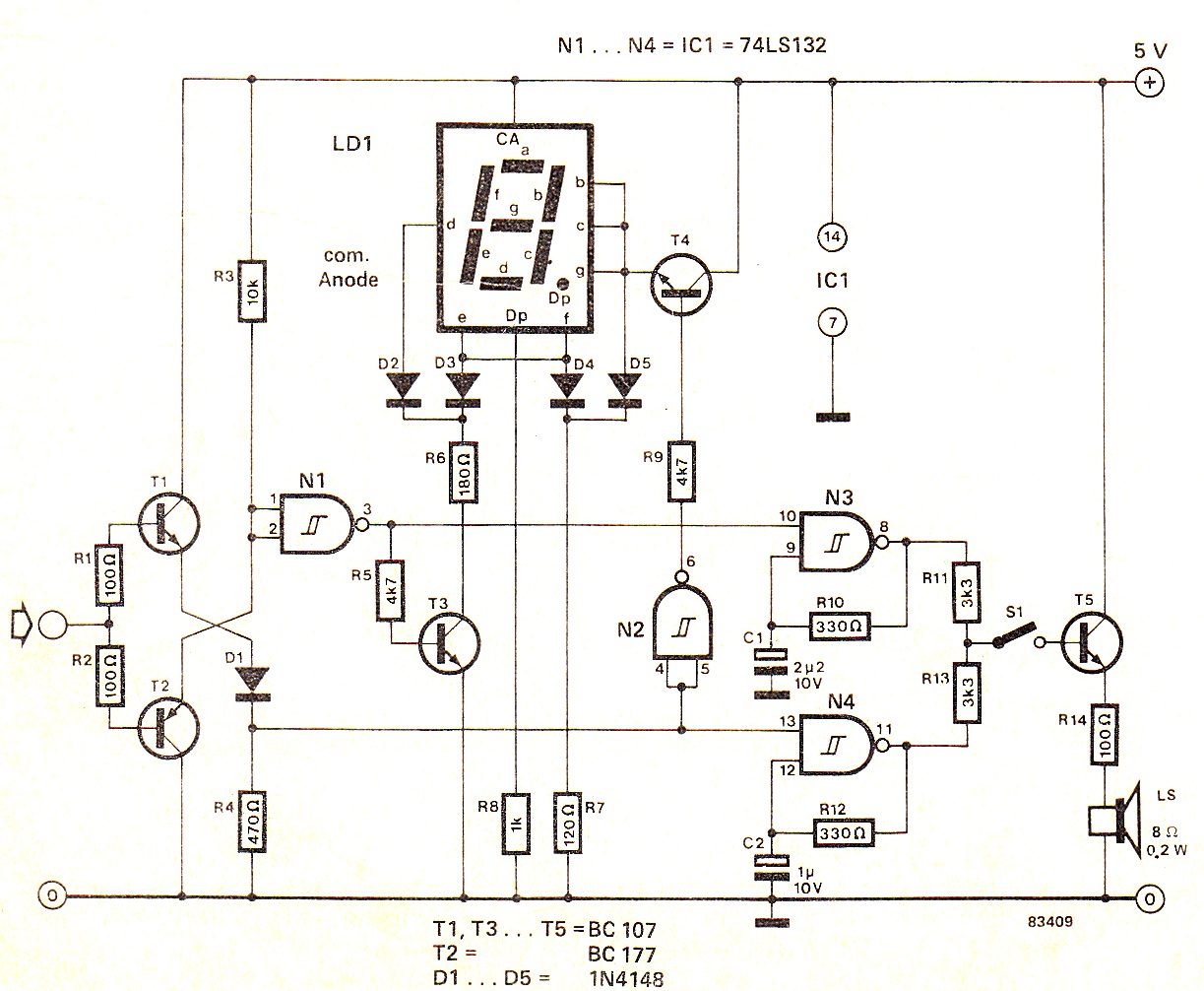
When the input signal is at logic high (1), the display indicates `H`, and the loudspeaker emits a note that is one octave higher than the low tone. The operation of the circuit can be observed in the circuit...