
Digital Capacitance Meter with RS232 interface circuit

SMD ceramic capacitors are widely used in modern electronic circuits due to their compact size and high performance. These components are typically found in applications ranging from consumer electronics to advanced communication systems. The absence of value markings on SMD capacitors presents a challenge in identifying their capacitance, necessitating the use of a capacitance meter for accurate measurement.
A capacitance meter operates by applying a known voltage across the capacitor and measuring the resulting charge. This process enables the meter to calculate the capacitance value based on the relationship defined by the formula \( C = \frac{Q}{V} \), where \( C \) is the capacitance in farads, \( Q \) is the charge in coulombs, and \( V \) is the voltage in volts.
When measuring SMD capacitors, it is crucial to ensure that the capacitance meter is set to the appropriate range to accommodate the expected values, which can vary from picofarads (pF) to microfarads (µF). Proper care should be taken to avoid introducing additional capacitance through the measurement leads, which can skew the results.
In circuit design, understanding the capacitance values of SMD ceramic capacitors is essential for achieving desired frequency response, filtering characteristics, and stability in power supply circuits. Therefore, accurate measurement and identification of these components play a vital role in the overall performance and reliability of electronic devices.Unlike almost all SMD resistors, the SMD ceramic capacitors are not marked with their values. To find the value of these capacitors we need a capacitance meter.. 🔗 External reference
Related Circuits
Lamp dimmer. The circuit illustrated below can be employed for dimming lamps. It utilizes a minimal number of components, which can be conveniently installed within the lamp socket. This circuit is typically utilized in RC phase shift configurations. The...
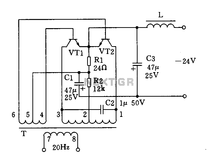
The circuit described is a 20Hz signal generator suitable for telephone ringing systems, alarm systems, and various other electronic applications. It consists of a transformer (T) and two transistors (VT1 and VT2), forming a push-pull oscillator. The two transistors...
The following circuit illustrates a LEGO Light Sensor Circuit Diagram. This circuit is based on the LM358 integrated circuit, which features a dual operational amplifier and high-speed capabilities. The LEGO Light Sensor Circuit utilizes the LM358, a versatile dual op-amp...
The acoustic spectrum extends from a very low frequency of 20 Hz to a high frequency of 20,000 Hz. At lower frequencies, the sense of direction diminishes. This observation leads to the recommendation of using speakers that handle very...
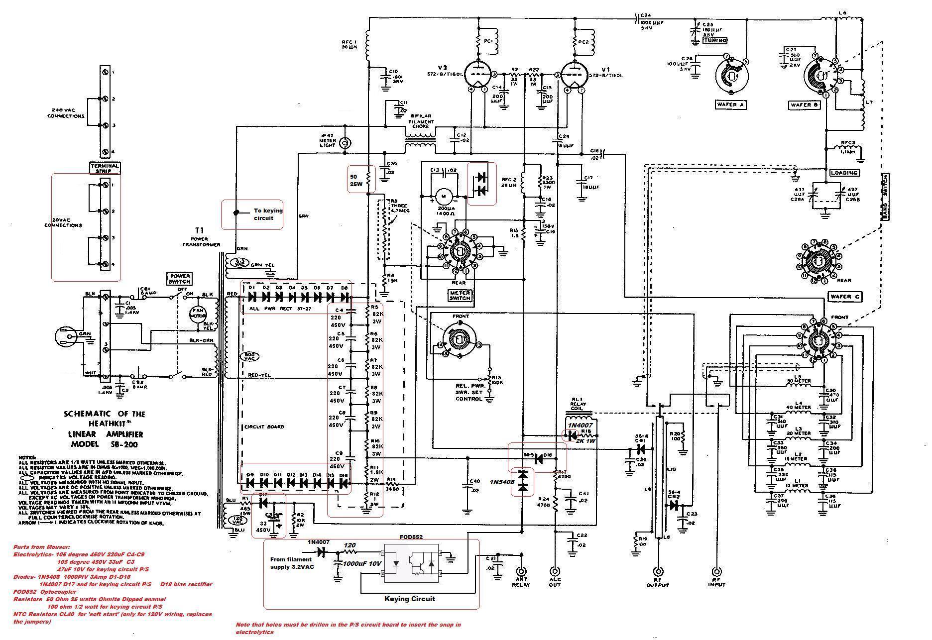
This circuit serves as a cost-effective alternative to commercially available keying circuits. It has been successfully implemented in the SB-200 amplifier. A schematic of the modified SB-200 is provided. The described circuit is designed to function as a keying mechanism...
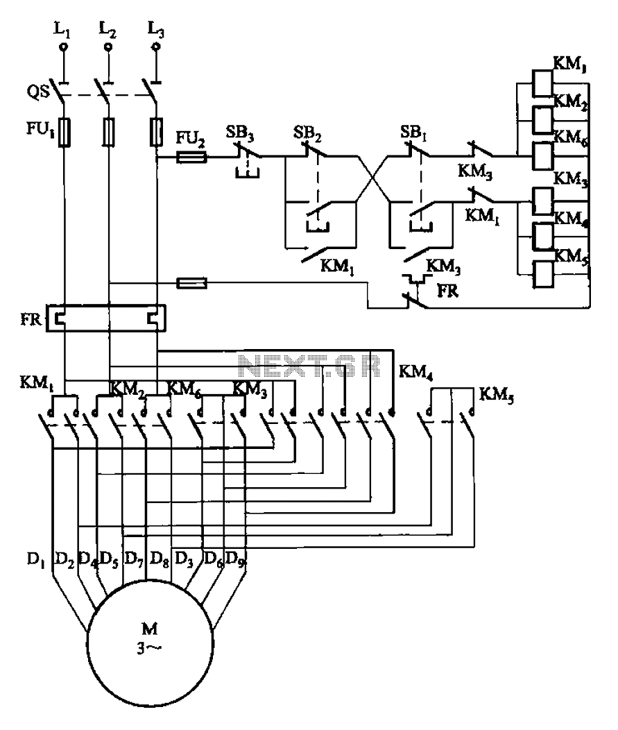
The circuit illustrated in Figure 3-107 features a low-speed operation button (SBi) and a high-speed operation button (SB2). The circuit design depicted in Figure 3-107 integrates two operational modes controlled by distinct buttons: SBi for low-speed operation and SB2 for...