
How to work with External Interrupts in AVR micro controller (Atmega8)
The Atmega8 microcontroller is a versatile device widely used in embedded systems, particularly for applications requiring external interrupt handling. External interrupts allow the microcontroller to respond immediately to external events, enhancing its ability to interact with the environment.
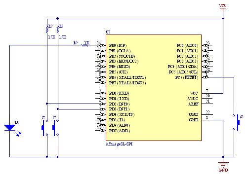
In this demonstration, the circuit is designed to showcase how an external interrupt can be triggered by a push-button switch. The circuit typically includes the Atmega8 microcontroller, a resistor, a capacitor, and the push-button switch connected to one of the external interrupt pins, such as INT0.
When the button is pressed, the voltage at the interrupt pin changes, signaling the microcontroller to execute the ISR. The ISR is a special function written in C that defines the actions to be taken when the interrupt occurs. For example, the ISR could toggle an LED, increment a counter, or send a signal to another part of the system.
The circuit diagram would illustrate the connections between the Atmega8 and the components, ensuring that the pull-up resistor is properly connected to maintain a stable high state until the button is pressed. The microcontroller's configuration registers must be set to enable the external interrupt and define its triggering condition (rising edge, falling edge, or both).
The C code would typically include the necessary header files, initialization of the microcontroller, configuration of the interrupt registers, and the ISR definition. The code should also contain a main loop that allows the microcontroller to remain in a low-power state or perform other tasks while waiting for the interrupt to occur.
This demonstration effectively illustrates the functionality of external interrupts in the Atmega8 microcontroller, providing a practical application for those learning about embedded systems and real-time processing.A demo of external interrupts in AVR (Atmega8) micro controller with circuit diagram and C code/program as ISR (interrupt service routine).. 🔗 External reference
Related Circuits
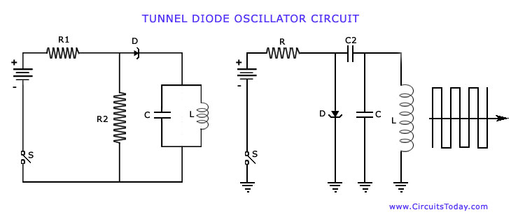
The operation of Negative Resistance Oscillators, including types such as Dynatron and Tunnel Diode Oscillator, along with their characteristics and circuit diagrams, is explained. Negative resistance oscillators are electronic circuits that exploit the phenomenon of negative resistance to generate oscillations....
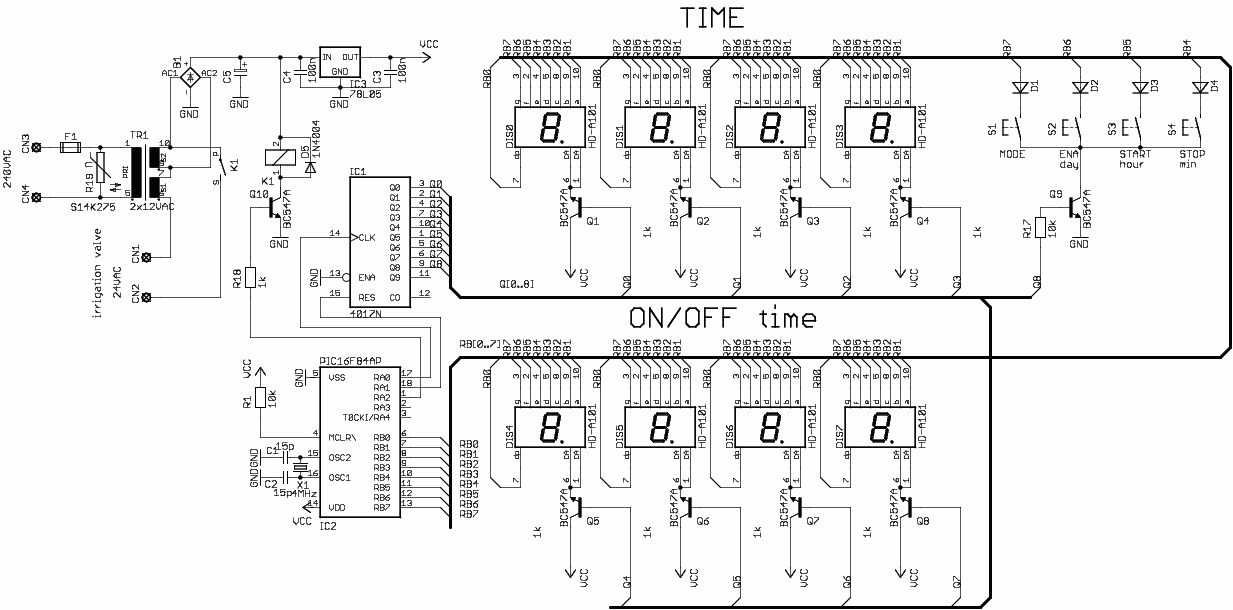
This is a simple one-valve irrigation controller made for our greenhouse. The code contains a software real-time clock (RTC) and a multiplexed 8-digit LED display and keyboard you can use in other projects. The operating software is simple, it...

This circuit is similar to the one found in the Single Buss 1V/Octave Keyboard Controller. Refer to the circuit description there for more details. This board includes additional resistors used in the keyboard voltage divider. In a typical keyboard,...
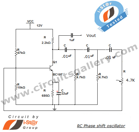
This section introduces a transistor oscillator circuit known as the RC Phase Shift Oscillator. An oscillator is an electronic circuit that functions as a sine wave generator, requiring only a DC power supply. It is commonly used in variable...
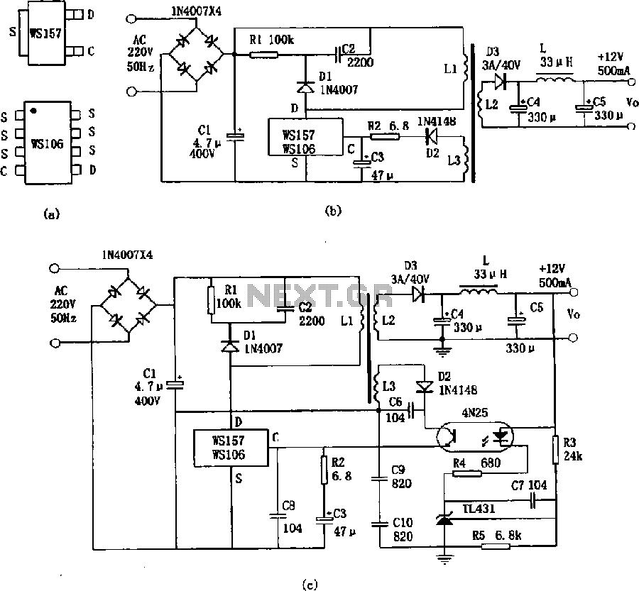
The WS157 or WS106 is a low-power miniature switching power supply that has been developed in recent years. It functions as a regulated switching power supply control device, featuring integrated internal control circuitry and power switches on a single...
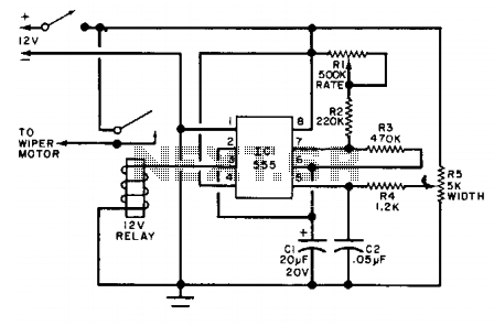
The relay that supplies power to the wiper motor is activated at regular intervals by the timer circuit, which closes the contacts for the wiper motor. Potentiometer R1 functions as the pulse rate control, while potentiometer R5 is used...