
MFOS Mini-Controller circuit

This circuit serves as a versatile platform for creating a keyboard controller with touch-sensitive pads. The integration of resistors in the voltage divider allows for accurate voltage readings corresponding to the keys pressed. The approach of connecting the bus to the divider via touch probes enhances the user experience by enabling a more intuitive interaction with the circuit.
The MFOS Wall Wart Power Supply's compatibility with the MFOS Mini-Controller is notable, as it simplifies the power management for connected devices like the Sound Lab Mini-Synth. The banana jacks serve as convenient connection points for power distribution, ensuring that the system remains modular and easily adaptable.
The design also accommodates potential expansions, as indicated by the unused PCB connection points. These can be leveraged if the user decides to transition from a touch-pad interface to a traditional keyboard setup. The inclusion of TLA, GLA, and KBTP connections facilitates this transition, allowing for the integration of additional features such as LED indicators for triggering and gating signals.
In summary, this circuit not only provides a functional keyboard controller but also offers flexibility for future modifications and enhancements, making it suitable for various applications within electronic music synthesis.This circuit is identical to the one in the Single Buss 1V/Octave Keyboard Controller. See the circuit description there. This board has the addition of the resistors used in the keyboard voltage divider. Whereas in typical keyboard pressing a key brings the resistor divider in contact with the main buss we bring the bus to the divider via the probe used to touch the PCB pads that represent the keyboard. As you can see in the photos above I combined the MFOS Wall Wart Power Supply with the MFOS Mini-Controller and also fed the +12V, -12V and Ground out via banana jacks so I can power my Sound Lab Mini-Synth. It is very convenient. You only connect the PCB points shown here and of course KBUS to the banana jacks so you can connect the wand to them.
There are several PCB connection points that are not used unless you score a real keyboard and then use this board to build a regular keyboard. Then you might want to use TLA (Trigger LED Anode), GLA (Gate LED Anode), and KBTP (keyboard top) as described in this article Single Buss 1V/Octave Keyboard Controller.
As far as the Mini-Controller circuit is concerned when you plan to use the touch pads everything is already pre-connected on the PC board and you just leave these as they are. You only connect the PCB points shown here. There are several PCB connection points that are not used unless you score a real keyboard and then use this board to build a regular keyboard.
Then you might want to use TLA (Trigger LED Anode), GLA (Gate LED Anode), and KBTP (keyboard top) as described in this article Single Buss 1V/Octave Keyboard Controller. As far as the Mini-Controller circuit is concerned when you use the key-pads everything is already pre-connected on the PC board and you do not need to connect the PCB connection points you see here with no wires going to them.
Additionally if you use this PCB for a keyboard you would remove the LEDs, and the keyboard voltage ladder resistors. 🔗 External reference
Related Circuits
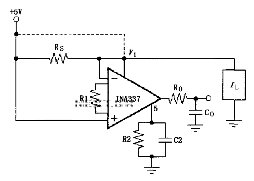
The INA337 circuit, as illustrated, is part of a load current measuring shunt circuit. It generates a voltage drop across the sampling resistor Rs, which is connected in series between the power source and the load. The load current...
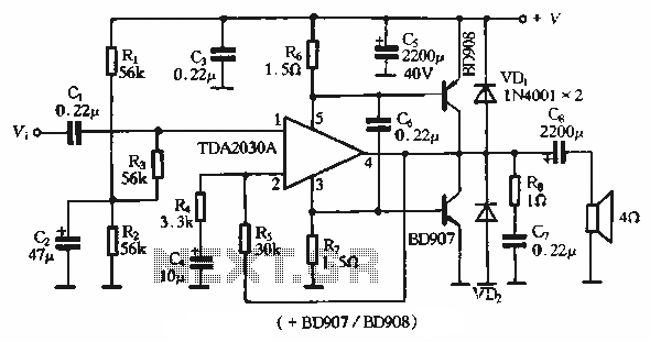
The rDA2030A TDA2030 is an enhanced version of the original product, with a maximum working voltage increased to 18V and a maximum output power of 18W. Additionally, harmonic distortion has been significantly reduced. The application circuit is illustrated. The rDA2030A...
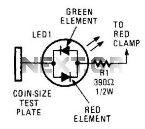
This circuit comprises a tri-color LED, a resistor, wire, and a coin-sized test plate. Two circuits must be constructed, one for each black clamp on a set of auto battery jumper cables. The circuits are installed inside the black...
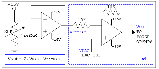
As mentioned in the chapter about the DAC, this circuit shifts the voltage output range. The following diagram explains its operation and structure. The circuit's outputs are connected to the input pins of the power operational amplifiers. The described circuit...
The video master comprises a series of converters that allocate all video sources to unused UHF channels. These channels are then combined with standard TV channels, whether terrestrial or cable, into a single cable. This single cable can subsequently...
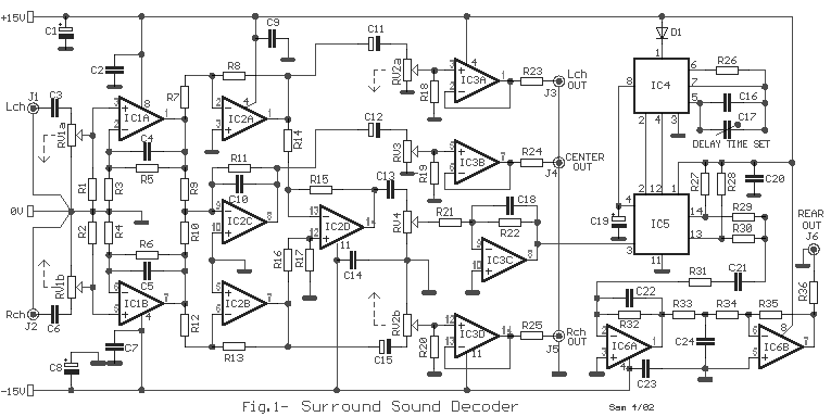
The circuit operation begins by transmitting stereo surround sound signal quality information through the master volume circuit. This drives the left channel connected to the LCH Model TL072 IC1A and IC1B, which are linked to the right channel (Rch)....