
Greenhouse irrigation controller ( PIC16F84 )
")
The irrigation controller circuit comprises a microcontroller unit (MCU) that integrates both the real-time clock (RTC) functionality and the control logic for the irrigation valve. The MCU is programmed to manage the scheduling of the valve based on user-defined parameters, which include the duration of watering, the interval between watering sessions, and specific start times.
The user interface consists of a multiplexed 8-digit LED display, which serves to present the current time, scheduled activation times, and the valve state (ON/OFF). The display is driven by the MCU through a series of output pins that control the individual segments of the LED digits. A keypad interface allows users to input their settings, including the MODE button for cycling through various configuration options, the ENABLE button to toggle scheduling, and the START/STOP buttons for manual control of the irrigation process.
Data storage for the scheduling parameters is facilitated by the EEPROM (Electrically Erasable Programmable Read-Only Memory), which retains the configuration even during power loss. This ensures that the irrigation schedule is preserved and does not require reprogramming after a power outage.
The valve control is executed via a relay or a transistor switch, which is activated by a digital output from the MCU. The relay or transistor is responsible for controlling the power to the irrigation valve, allowing it to open or close based on the programmed schedule.
Additionally, the system includes feedback mechanisms to monitor the valve state, which is indicated on the display. The second line of the display shows the activation or stop time, along with a visual indicator (such as a dot) that signifies whether the valve is currently active or inactive.
Overall, this one-valve irrigation controller is designed for efficiency and ease of use, making it a suitable solution for automated irrigation in greenhouse settings.This is a simple one-valve irrigation controller made for our greenhouse. The code contains a software real-time clock (RTC) and a multiplexed 8-digit LED display and keyboard you can use in other projects. The operating software is simple, it contains a real-time clock and a day counter. The valve is turned on in regular intervals in the same time. Day setting specifies the number of days between the activations, time setting specifies the time of the day when to start.
Duration is the time after which the valve will be turned off. MODE button cycles through clock, start time and duration settings. the interval and starting time set will be stored in the DATA EEPROM. Scheduling can be totally turned OFF by the ENABLE button. Irrigation can be manually turned ON/OFF any time by the START/STOP buttons Activation/STOP time is displayed in the second line of display. Valve state (ON/OFF) is displayed in the second line, last dot 🔗 External reference
Related Circuits
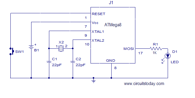
This article explains how to add a 32K external crystal/clock source to the Atmel AVR microcontroller Atmega8, including a circuit diagram and a C program. The Atmel AVR microcontroller Atmega8 is a popular choice for various embedded applications, often requiring...
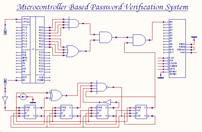
An 8-bit password serves as the input to this system. The password entered by the user is compared with the actual password, which is set in the microcontroller through a microprogram. The outcome of this comparison process generates an...
The MIC2199 is a synchronous buck switching regulator controller. It features an all N-Channel synchronous architecture and powerful output drivers that enable a maximum output current capability of 20A. The device operates with an input voltage range of 4.5V...
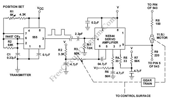
This is a servo system controller circuit designed for remote control of a servo motor. The circuit utilizes a 555 timer and requires only six additional components. The servo system controller circuit operates by generating a pulse-width modulation (PWM) signal,...

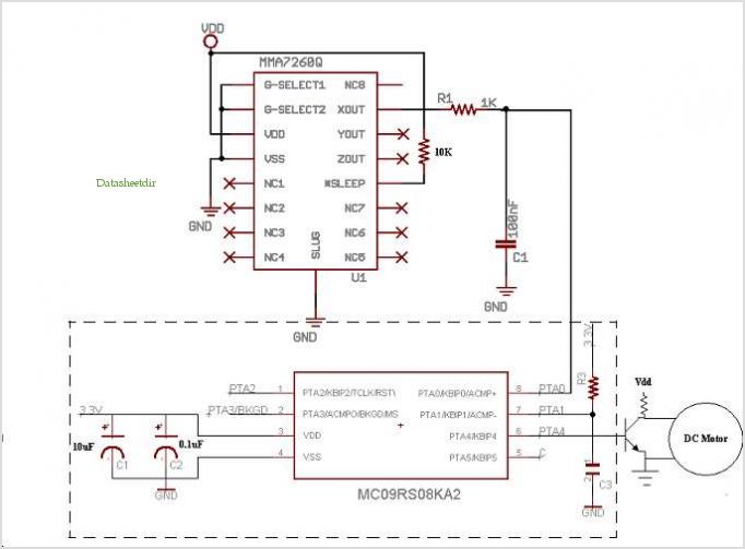
This document discusses the use of small microcontrollers, such as those from the PIC and Atmel series, which typically operate at 5V and require less than 100mA for complete system functionality. Some PICs can function at lower voltages, such...
This add-on circuit enables remote switching on/off of battery-operated toy cars using a TV/video remote control handset operating at 3040 kHz. The described circuit utilizes a remote control system to facilitate the wireless operation of battery-powered toy cars. The primary...