
hp max2338 mixer if saw filter match at 183 6mhz for cdma
The 183.6 MHz SAW filter serves a critical role in CDMA applications, where precise frequency selection and signal integrity are paramount. The filter's S-parameters, which characterize its response in terms of reflection and transmission coefficients, are essential for simulating the behavior of the filter within the overall circuit. The integration of the SAWTEK 855893 SAW filter into the design necessitates careful consideration of the impedance matching between the filter and the MAX2338 mixer.
The design process begins with establishing the required source differential impedance, which is typically several hundred ohms for an IF SAW filter. The MAX2338 mixer, known for its high performance in CDMA applications, has an optimum load impedance in the range of 2kΩ to 3kΩ, contingent on the IF frequency. This discrepancy between the filter and mixer impedances necessitates the implementation of a high-to-low impedance transformation circuit to achieve optimal matching and performance.
The initial phase of the design involves performing S-parameter simulations using the mixer’s differential equivalent circuit at the target IF frequency. The four-port S-parameter data provided by the SAW filter manufacturer is integrated into the simulation to evaluate the filter's performance without any external matching circuits. This simulation phase allows for the identification of critical parameters such as insertion loss and amplitude ripple, which are crucial for maintaining the integrity of the CDMA signal.
Incorporating real-world PCB characteristics into the simulation enhances the accuracy of the model. Factors such as transmission line lengths, substrate thickness, and dielectric properties must be considered to ensure that the simulated performance closely matches the actual circuit behavior. The correlation between the simulated and measured performance of the MAX2338 mixer gain and the SAW filter insertion loss is a testament to the effectiveness of the initial design efforts.
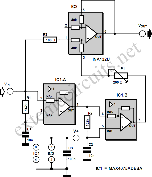
However, it is important to note that the final circuit may require minor adjustments to the component values derived from simulation. These adjustments are necessary to account for any discrepancies arising from unmodeled board characteristics or variations in component tolerances. The overall design process emphasizes the importance of iterative testing and refinement to achieve the desired performance in the final application.183. 6MHz SAW filter in a CDMA application. The SAW filter S-parameter is used to simulate the interface with the mixer. A worked example is provided with a SAWTEK 855893 SAW filter. An optimum impedance matching circuit between the MAX2338 mixer differential IF ports and a 183. 6MHz CDMA IF SAW filter is presented in this application note. A practi cal HP-ADS simulation schematic file along with test measurement results are included. Optimization criteria is based on minimum filter insertion loss, peak-to-peak amplitude ripple, and highest mixer IIP3 performance. Typically, an IF SAW filter wants to see a source differential impedance in the order of several hundred ohms.
The MAX2338 CDMA mixer output trans conductance stage`s optimum load is in the order of 2k © to 3k © as a function of IF frequency. Therefore, a high to low impedance transformation topology is needed for an optimum match. Initial S-parameter linear simulation is performed based on the mixer differential equivalent circuit at the intended IF frequency of operation and the four-port S-parameter of the SAW device (without any external matching circuits) supplied by the SAW manufacturer.
Actual product platform PCB information such as embedded transmission line lengths, substrate thickness, dielectric material, and size characteristics, can all be incorporated in the simulation for accurate modeling. Component values derived from simulation and subsequently implemented on circuit board on the first attempt demonstrated very good correlation between the MAX2338 mixer gain and SAW filter insertion loss.
Final circuit implementation may require slight deviation from simulated component values to account for board that have not been modeled. 🔗 External reference
Related Circuits
A notch filter designed for a narrow frequency band of a few percent or less typically requires close-tolerance components. This assumption was challenged upon discovering a specialized operational amplifier integrated circuit (IC) from Maxim. In filters with steep slopes,...
The use of optical filters to reduce or eliminate light from other sources is discussed. A narrowband optical filter on the receiver can reject "off-wavelength" light; however, these filters tend to be expensive and challenging to implement in simple...
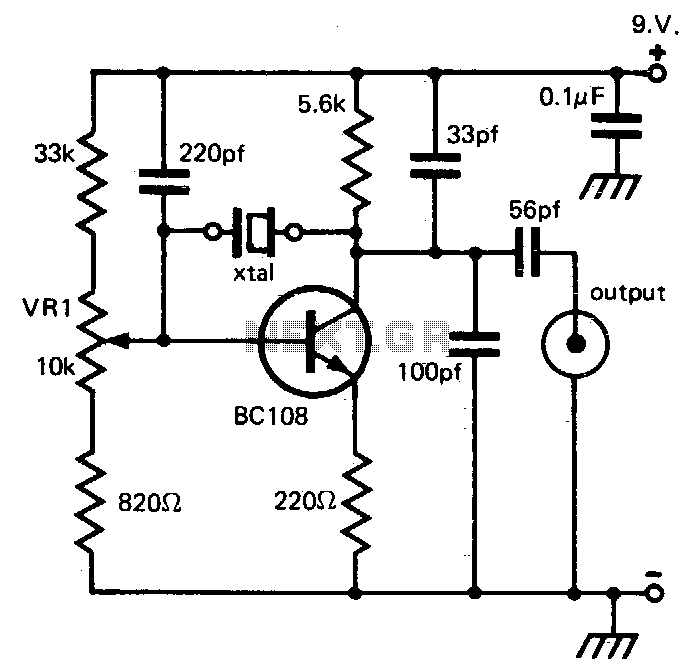
This circuit provides reliable oscillation and an output close to one volt peak-to-peak. Power consumption is around 1 mA from a nine-volt supply. The described circuit is likely a simple oscillator designed to generate a periodic waveform with a peak-to-peak...
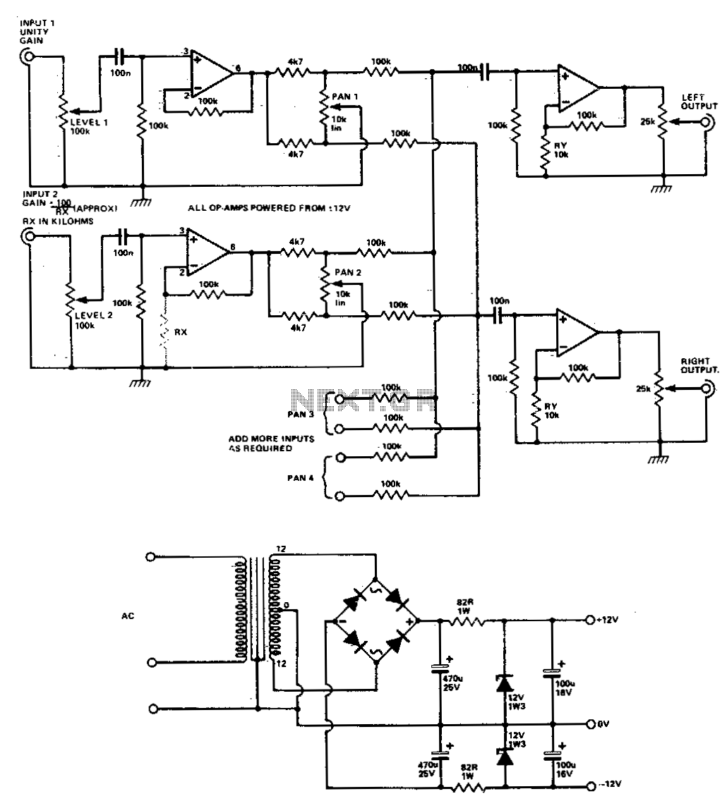
Four or more inputs can be mixed to produce stereo output. The gain of each stage can be increased by adding RX, but it should be kept below 50 (with RX above 2 K) to avoid poor frequency response....
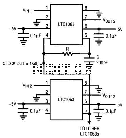
The LTC1063 is a monolithic low-pass filter that provides exceptional DC and AC performance. It features both internal and external clock tunability, with cutoff frequencies reaching up to 50 kHz, a typical output DC offset of 1 mV, and...
If the transmitter stick-potentiometer delivers a voltage about 2 - 3 V, this circuit will be suitable. If you want to avoid using the battery cable (supplying Vcc for IC1 and -2), you can use a separate 5V supply...