
Butterfly Mixer Circuit
This circuit description pertains to a transmitter system utilizing a stick potentiometer to manage control surfaces in an RC aircraft. The stick potentiometer is designed to output a voltage in the range of 2 to 3 volts, which is suitable for interfacing with the circuit components. The circuit integrates operational amplifiers or integrated circuits (ICs) designated as IC1 and IC2, which can be powered either by a battery or an external 5V supply.
To enhance reliability, especially under conditions of low battery voltage, an external power source for IC1 and IC2 is recommended. This configuration allows for stable operation of the circuit, ensuring that the mixer function remains effective even when the battery voltage diminishes.
In the application of this circuit as a butterfly mixer, it is crucial to note the substitution of control inputs. The rudder potentiometer typically used in standard configurations is replaced by an aileron potentiometer, allowing for differential control of the aircraft's roll. Additionally, the elevator potentiometer is omitted in favor of a simplified circuit, which may include a direct connection to the control signal or an alternative method of signal processing suitable for the specific application.
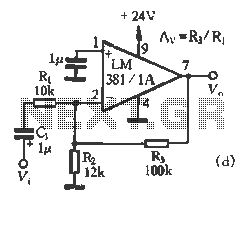
The design of the circuit should include proper filtering and amplification stages to ensure that the output signals are clean and adequately drive the control surfaces. The incorporation of decoupling capacitors at the power supply pins of the ICs is also advisable to minimize noise and enhance performance.If the transmitter stick-potentiometer delivers a voltage about 2 - 3 V, this circuit will be suitable. If you want to avoid using the battery cable (supplying Vcc for IC1and -2), you can use a separate 5V supply for IC1 and -2.
In that case you should test the mixer function when the battery voltage is low. If the circuit is used as a butterfly mixer, instead of the rudder potentiometer the aileron potentiometer must be connected, and instead of the elevator potentiometer the following simply circuit can be used: 🔗 External reference
Related Circuits

Daylight shutoff; the schematic has been updated but is not shown here. The daylight shutoff circuit is designed to automatically turn off lighting systems during daylight hours, thereby conserving energy and extending the lifespan of the lighting fixtures. Typically, this...
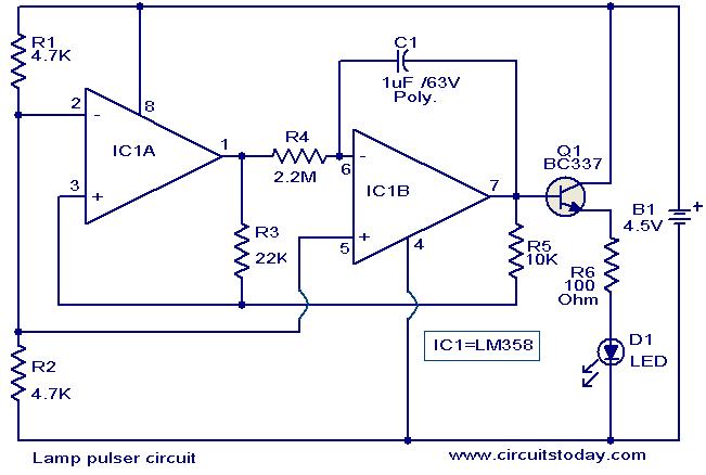
This circuit is designed to gradually pulse an LED or a low-power filament lamp, creating a visual effect where the light transitions from an OFF state to full brightness and then back down to OFF. Such a circuit is...
The LM1036 is a DC-controlled circuit designed for managing tone (bass/treble), volume, and balance in stereo applications, such as car radios, televisions, and audio systems. It features an additional control input for easy loudness compensation. Four control inputs allow...
National Semiconductor (NS Company) produces audio integrated circuits (ICs) that offer wide frequency response and low noise. These circuits provide excellent performance across all NS products. The circuit illustrated in Figure 3-12 includes a preamplifier and a singing equalizer...
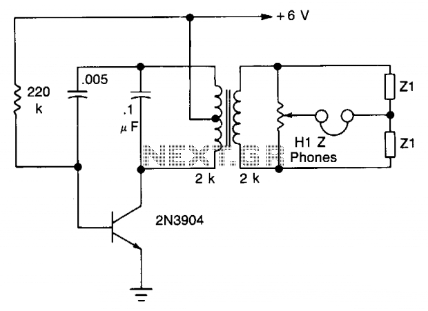
The transistor is configured as an audio oscillator, utilizing an audio transformer in the collector. The secondary winding is connected to a linear potentiometer. The ratio between the two sections of the potentiometer from the slider is proportional to...
This is a simple magnetic levitation circuit that suspends objects at a specified distance below an electromagnet. The underlying physics involves providing a magnetic force that counteracts gravity. The magnetic levitation circuit operates by utilizing an electromagnet, which generates a...
Warning: include(partials/cookie-banner.php): Failed to open stream: Permission denied in /var/www/html/nextgr/view-circuit.php on line 713
Warning: include(): Failed opening 'partials/cookie-banner.php' for inclusion (include_path='.:/usr/share/php') in /var/www/html/nextgr/view-circuit.php on line 713