
Human detector circuit
The circuit employs a PUT (Programmable Unijunction Transistor) Complimentary Feedback Pair configuration with transistors Tr1 and Tr2 acting as the sensitive electric field detectors. The detection mechanism is based on the principle that any charge difference between the two points A1 and A2 generates a small current that flows into the bases of Tr1 and Tr2, thus turning them on. This allows current to flow through resistors R1, R2, R3, and R4, which in turn activates transistor Tr4, initiating the oscillator circuit.
As Tr4 turns on, capacitor C1 begins to charge. The charging threshold of C1 is determined by resistors R1 and R2. Once C1 reaches a sufficient voltage, transistor Tr3 is activated, which diverts current from the base of Tr1, effectively turning off the PUT pair. With the PUT pair deactivated, Tr4 is also turned off, but not before discharging capacitor C2. This capacitor now maintains the base current to the oscillator, causing a gradual decrease in the oscillator frequency, which produces an interesting sound effect.
The oscillator itself is built around transistors Tr5 and Tr6, which receive feedback through capacitor C3 and resistor R9. Initially, with Tr4 off and C2 charged, both Tr5 and Tr6 are in a non-conducting state, and C3 remains uncharged. When Tr4 is activated, both Tr5 and Tr6 start conducting, with additional base current supplied to Tr6 from the charging C3. As C3 charges, it causes a slight change in Tr5's collector current, which generates a small signal into Tr6, leading to oscillation due to positive feedback.
The output stage is formed by transistors Tr6 and Tr7, configured in a totem-pole arrangement, which drives a small loudspeaker. While the original design utilized a magnetic earpiece from a vintage telephone, any small loudspeaker can be employed as a replacement.
Construction of this circuit should be approached with caution, especially concerning the front-end components (Tr1, Tr2, and Tr4), which are sensitive to environmental electric fields. It is advisable to use PTFE stand-off terminals for these components, allowing them to be mounted in free air rather than on a circuit board, thereby minimizing interference from surrounding electrical noise.This is a circuit thich I originally included in my book, 22 Tested Transistor Projects, published by Babani Press in 1976 (ISBN 0 900162 63 S). It is one I had great fun with. It uses the PUT Complimentary Feedback Pair as a sensitive detector of changing electric fields to switch on an oscillator and make a noise.
It is so sensitive that it can be difficult to get it working on a test bench because of all the electric fields, but put it on a table and leave it. Then when you walk up to it, your movement is likely to cause enough field change to trigger it. Triggering not only depends on how fast you approach it but also on the clothes you are wearing, the relative humidity and your own body capacity and skin conductivity, so it reacts differently to different people.
Some it reacts to not at all, others cannot even approach it. Tr1 and Tr2 are a PUT Complimentary Pair as explained on that circuit's page. Any charge difference between A1 and A2 causes a few electrons to flow into the transistor bases and they both turn on allowing current through R1-R2-R3-R4. Tr4 turns on, starting the oscillator and causing C1 to start charging. When C1 has charged enough (set by R1 and R2) Tr3 turns on and robs the current from Tr1's base, turning off the PUT pair.
When they turn off, Tr4 is no longer turned on bit it has already discharged C2, which now charges up by maintaining base current to the oscillator and as it charges the oscillator's frequency dies. This changing oscillator frequency actually causes a very interesting sound. This voltage controlled oscillator consists of Tr 5 and Tr 6 with feedback via C3, R9. Initially with Tr4 off and C2 charged, Tr5 and Tr6 are both off and C3 is uncharged. When Tr4 turns on, Trs and Tr6 both conduct with additional current supplied to Tr6's base via C3 which starts to charge.
When C3 is charged, there is just enough change in Tr5's collector current that a small signal is fed into Tr6 and the loop gain is high enough so that it starts to oscillate via the overall positive feedback. Tr6 with Tr7 form a 'Totem-pole' output stage to drive a small loudspeaker. The original used a magnetic earpiece out of an old telephone handset, but these are maybe not obtainable.
Any small loudspeaker should work. You must take extreme care with building this circuit, at least with the front end, Tr1 and Tr2 collectors and bases and Tr4's collector: these are the bits attached to A1 and A2 and are marked in red. Ideally you should use two PTFE stand-off terminals for these and connect the three transistors to them in the air, not via a circuit board.
🔗 External reference
Related Circuits

Drawing transistors that comprise the gate VTi, VT2, VT3, and similar components. The schematic involves a configuration of transistors designated as VTi, VT2, and VT3, which are integral to forming a gate structure. These transistors are typically arranged in a...
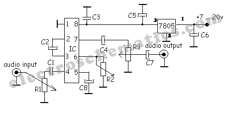
A simple audio compressor is designed using the SSM2165 integrated circuit (IC). There is limited explanation available regarding the schematic of this compressor circuit; however, special attention should be given to the capacitor used. The audio compressor circuit utilizing the...

The MAX233 / 233A is a multi-channel data interface circuit featuring dual output and dual input driver circuits. It is designed for small digital products and multimedia equipment to facilitate data transmission. The MAX233 / 233A integrates multiple functions to...
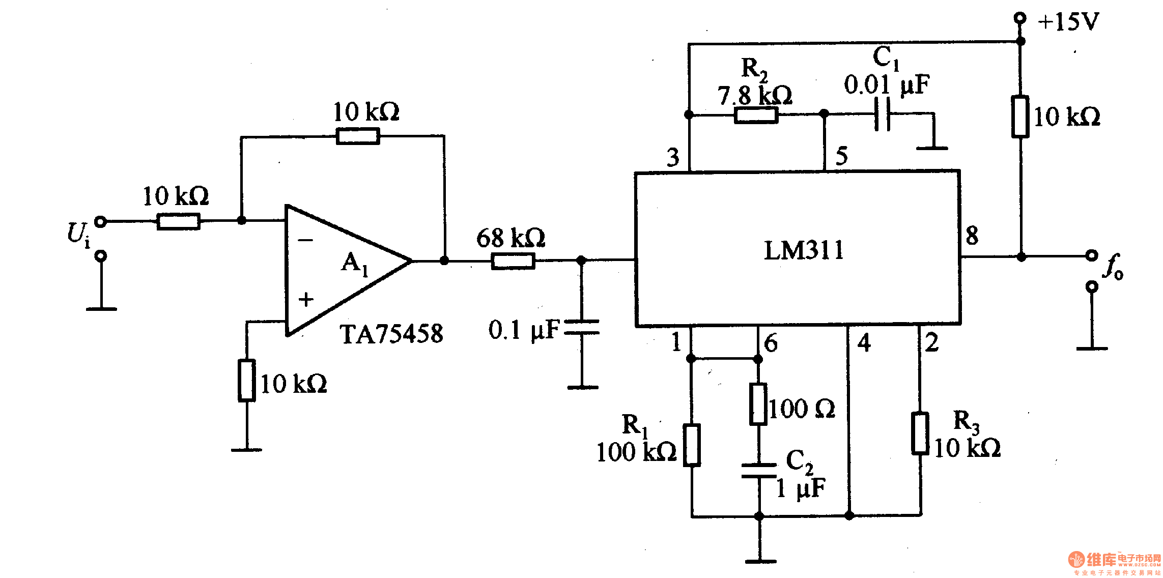
The LM311 is an integrated circuit that functions as a reference voltage generator, comparator, amplifier, and discharge circuit. It is designed for ease of use. In the circuit, the output frequency f0 is... The LM311 is a versatile integrated circuit...

The circuit demonstrates the application of the ZN414 integrated circuit (IC) to create a compact AM radio receiver. The ZN414 IC is a combination of a transistor and a tuned radio frequency (TRF) circuit. The ZN414 IC is specifically designed...

A car battery deteriorates in use, and its life seldom exceeds four years. When new, its voltage may drop to only 2V while cranking the engine. A car battery, typically a lead-acid type, is essential for providing the necessary electrical...
Warning: include(partials/cookie-banner.php): Failed to open stream: Permission denied in /var/www/html/nextgr/view-circuit.php on line 713
Warning: include(): Failed opening 'partials/cookie-banner.php' for inclusion (include_path='.:/usr/share/php') in /var/www/html/nextgr/view-circuit.php on line 713