
Audio Compressor Circuit with SSM2165
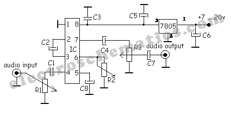
The audio compressor circuit utilizing the SSM2165 IC is designed to manage audio signal levels by reducing the dynamic range of the input signal. The SSM2165 is a low-voltage audio compressor that provides a cost-effective solution for audio applications requiring compression, such as in mixing consoles, broadcast audio, and musical instrument amplifiers.
The schematic typically includes the SSM2165 IC, which handles the compression process. Input audio signals are fed into the IC, where they are processed according to the compression ratio set by external components. The capacitor plays a crucial role in this circuit, as it affects the attack and release times of the compressor. Selecting the appropriate capacitance value is essential for achieving the desired response characteristics.
In addition to the capacitor, resistors are also used to set the threshold and gain of the compressor. The output of the SSM2165 is connected to an output stage, which may include additional filtering or amplification stages to ensure that the audio signal is suitable for further processing or amplification.
Power supply considerations are important, as the SSM2165 operates within a specific voltage range. Adequate decoupling capacitors should be placed near the power pins of the IC to maintain stable operation and minimize noise.
Overall, this simple audio compressor circuit is effective for controlling audio levels, enhancing sound quality, and preventing distortion in audio signals, making it a valuable tool in various audio processing applications.A very simple audio compressor built with SSM2165 IC. There is no much explication about this compressor circuit schematic, just pay attention at capacitor.. 🔗 External reference
Related Circuits
This simple circuit combines two or more audio channels into a single channel (for example, mixing stereo into mono). The circuit is capable of mixing an arbitrary number of channels while consuming minimal power. Although the schematic illustrates two...
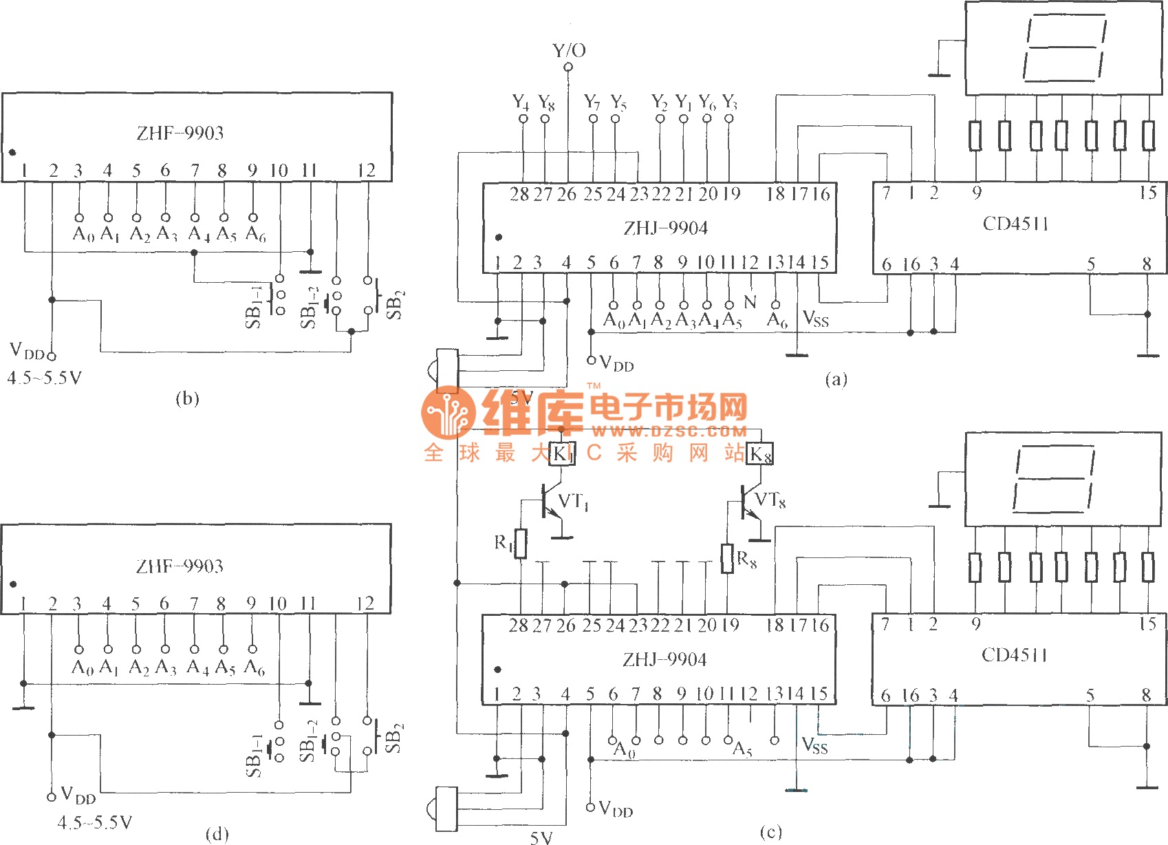
This is an eight-way signal remote control selection circuit composed of ZHJ-9904. It includes a remote control transmitter circuit, an eight-way switch control circuit, and a remote control transmitter. The eight-way signal remote control selection circuit utilizing the ZHJ-9904 is...
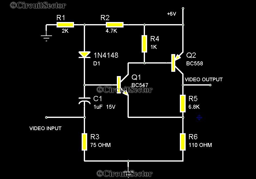
There are instances when it is necessary to view video clips captured by a digital camera on a television. This can be accomplished by connecting the camera's video output to the television's video input. However, a direct connection is...
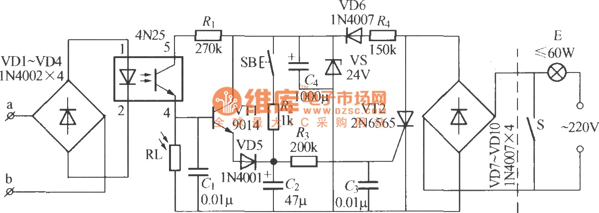
The diagram illustrates an automatic lighting control circuit activated by a telephone. At night, when the telephone rings or the user picks up the receiver, the light turns on. If the telephone stops ringing (when no one is listening)...
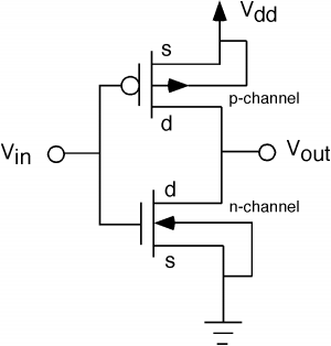
The fundamental issue presented is the perception that logic gates in a circuit seem to generate power from nothing, which contradicts the principles of physics. For instance, consider two NOT gates connected in series. It appears that the first...
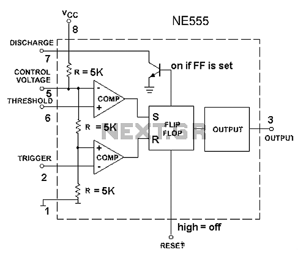
The 555 timer circuit, regardless of the manufacturer, has a consistent internal structure and performance. Various manufacturers produce different models of the 555 timer, including MC555, CA555, XR555, LM555, as well as domestic models like SL555, FX555, and 5G1555....
Warning: include(partials/cookie-banner.php): Failed to open stream: Permission denied in /var/www/html/nextgr/view-circuit.php on line 713
Warning: include(): Failed opening 'partials/cookie-banner.php' for inclusion (include_path='.:/usr/share/php') in /var/www/html/nextgr/view-circuit.php on line 713