
Humidty Sensor To Data Aquisition System Interface

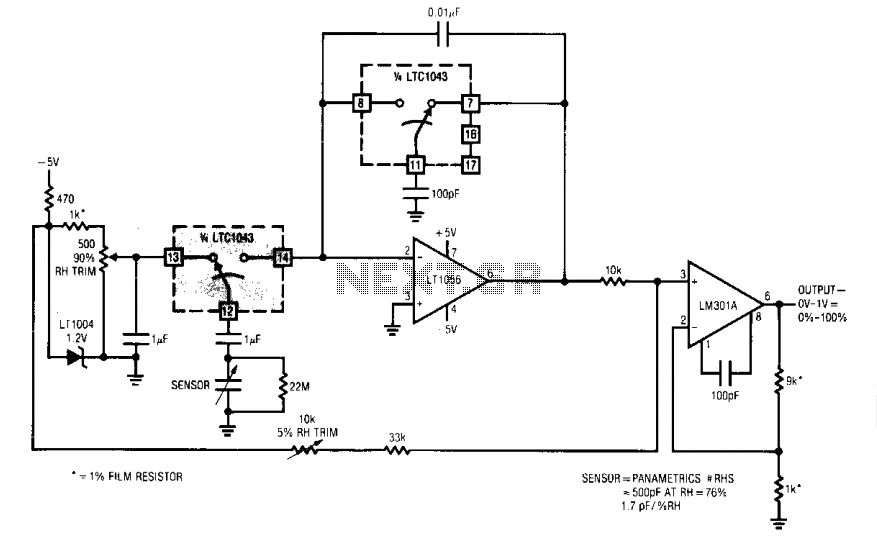
U2A, which is part of the LTC1043 switched capacitor building block, provides excitation for the sensor by alternating between 5V and -5V at a frequency of approximately 2.2kHz. This frequency is adjustable, but it is advisable to keep it below 2.4kHz, as this is half the auto-zero rate of U3.
The circuit employs zero-drift operational amplifiers, which are essential for applications requiring high precision and stability. The LTC1250 and LTC1050 amplifiers are designed to minimize offset voltage and drift, ensuring that the output remains stable over time and temperature variations. This is particularly advantageous in low-level signal applications where even minor fluctuations can lead to significant errors.
The LTC1043 serves as a switched capacitor block, which is a critical component for achieving the desired signal conditioning. It is capable of performing various functions, such as filtering and amplification, while maintaining high accuracy. The switched capacitor technique allows for precise control over the gain and bandwidth of the circuit, making it suitable for a wide range of applications.
The design's reliance on a single 5V power supply simplifies the power management requirements, reducing complexity and potential points of failure. The LTC1046's role in generating the negative voltage (-5V) is crucial for powering the operational amplifiers, as many precision amplifiers require dual supply voltages to operate effectively.
U2A's function in providing excitation to the sensor is vital for ensuring accurate readings. The switching between 5V and -5V at a frequency of 2.2kHz allows for dynamic signal processing, which can enhance the performance of the sensor system. The recommendation to keep the switching frequency below 2.4kHz is important for maintaining the integrity of the auto-zero function in U3, which is responsible for eliminating offset errors in the measurement system.
Overall, this circuit design exemplifies a careful balance between cost, performance, and accuracy, making it suitable for applications that demand high precision in low-voltage environments.The circuit shown in the schematic features zero drift operational amplifiers (LTC1250 and LTC1050) and a precision instrumentation switched capacitor block (LTC1043). This design will maintain excellent DC accuracy down to microvolt levels. This method was chosen over the use of a true RMS-to-DC or log converter because of the expense and temperature sensitivity of these parts.
Only a single 5V power supply is required. Integrated circuit U1, an LTC1046, converts the 5V supply to – 5V to supply power to U2, U3 and U4. U2A, part of an LTC1043 switched capacitor building block, provides the excitation for the sensor, switching between 5V and – 5V at a rate of approximately 2.2kHz. This rate can be varied, but we recommended that it be kept below approximately 2.4kHz, which is one-half the auto zero rate of U3.
🔗 External reference
Related Circuits
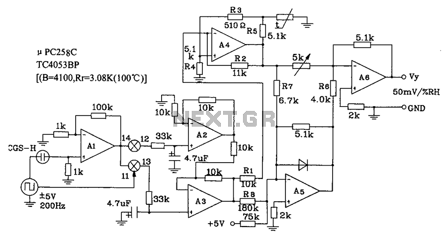
CGS-H ceramic humidity sensor constructed low humidity detection circuit diagram. The CGS-H ceramic humidity sensor is designed to detect low humidity levels within a specified range. This sensor operates on the principle of changes in capacitance that occur with variations...
A humidity sensor can be utilized to provide an alert for boat leakage or to notify when books are at risk of being damaged due to heavy rain affecting a compromised roof. Humidity sensors are essential devices that measure the...
When the 14B-12B pair opens, 12B is connected to Al's summing point via 13B. The sensor now discharges into the summing point through the 1 µF capacitor. Since the charge voltage is fixed, the average current into the summing...
The AmpLoadPull project demonstrates the utilization of the AmpLoadPull and LoadPullSetup components in Advanced Design System (ADS). These components are part of the ADS behavioral model suite located within the System - Data Models palette. The schematic "circuit_level_amplifier_1_tone.dsn" represents...
A rain sensor alarm circuit is a useful device for alerting when rainfall occurs. The rain detector circuit presented is straightforward, utilizing only three components while maintaining high sensitivity to detect rain or moisture. The sensor can be constructed...
A color sensor is an engaging project for hobbyists. This circuit can detect eight colors: blue, green, and red (primary colors); magenta, yellow, and cyan (secondary colors); as well as black and white. The circuit operates based on the...
Warning: include(partials/cookie-banner.php): Failed to open stream: Permission denied in /var/www/html/nextgr/view-circuit.php on line 713
Warning: include(): Failed opening 'partials/cookie-banner.php' for inclusion (include_path='.:/usr/share/php') in /var/www/html/nextgr/view-circuit.php on line 713