
rain sensor alarm circuit
The rain sensor alarm circuit is designed to provide an effective warning system for rainfall detection. The circuit's simplicity is one of its key advantages, as it consists of only three primary components: the rain sensor, the BC547B transistor, and a buzzer. The rain sensor is typically created by placing two conductive strips in close proximity, which allows for the detection of moisture when raindrops bridge the gap between them. The recommended spacing of no more than one millimeter between the strips ensures that even small amounts of water can trigger the circuit.
The BC547B transistor operates in a switching mode in this application. When the sensor detects water, the resistance between the strips decreases, causing a small current to flow through the base of the transistor. This base current allows a larger current to flow from the collector to the emitter, effectively turning on the transistor. As a result, the 9V power supply is connected to the buzzer, which produces an audible alarm to alert the user of rainfall.
To enhance the circuit's reliability, it is advisable to include additional components such as resistors or diodes to protect the transistor from voltage spikes or to limit the current flowing through the buzzer. Moreover, the use of a waterproof enclosure for the sensor can increase its durability and effectiveness in outdoor environments. Overall, this rain sensor alarm circuit serves as a practical and efficient solution for monitoring rainfall, making it suitable for various applications such as garden irrigation systems, weather stations, or home automation systems.A rain sensor alarm circuit can be a very beneficial device for alerting when rainfall happens. The rain detector circuit shown here is very simple using only three components but is very sensitive to detect rain or moisture. The sensor part of the circuit can be easily made with verobaord or you can also make it in home by attaching thin metal st
rips on plastic or wood etc. The sensor can be made by several techniques, and performance of the circuit is also depends on the sensor. For better performance make sure to give no more than 1minimeter gap between the sensor strips. Working of the circuit is simple the transistor BC547B is working as a switch in this circuit when the water droplets fall on the sensor the transistor will become switched on and the 9V will start passing through the transistor which will activate the Buzzer.
🔗 External reference
Related Circuits
A two-phase servo motor features a field winding and a control winding. When there is a 90° phase difference between the two, it generates rotational torque. A potentiometer connected to the motor shaft measures the voltage difference between the...
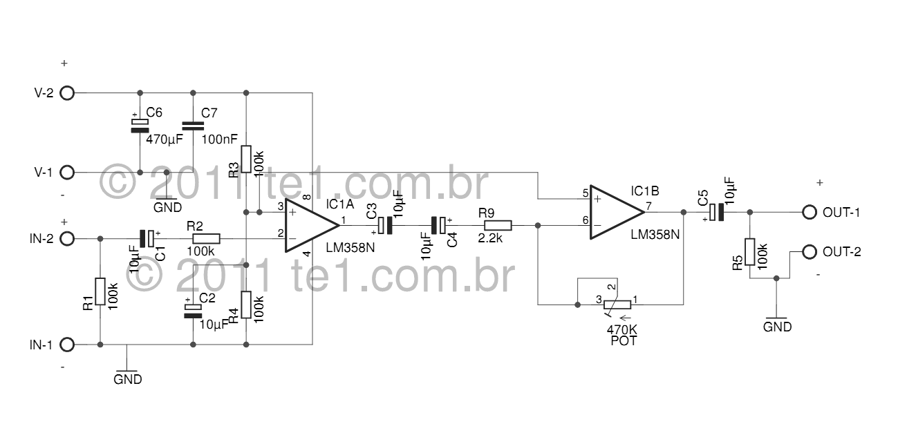
The LM358 series consists of two independent, high-gain, internally frequency-compensated operational amplifiers designed specifically to operate from a single power supply over a wide range of voltages. Operation from split power supplies is also possible, and the low power...
One of the most interesting projects to work with is that of a synthesizer that can accurately generate desired frequencies. This synthesizer uses just three CMOS chips and one PNP transistor. It is a fact that the transistor may...
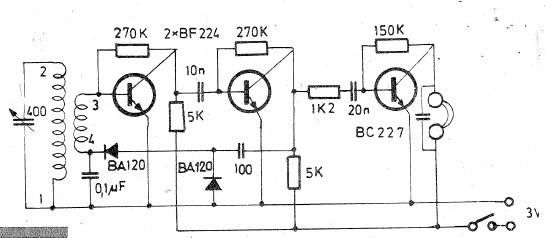
Oscillating circuits (coils) are constructed on a ferrite bar. For long wave reception, winding "1-2" consists of 135 turns, while winding "3-4" has 20 turns. For medium wave reception, winding "1-2" has 75 turns, and winding "3-4" has 7...
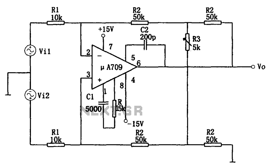
The configuration of the variable gain A709 differential amplifier circuit is illustrated. The primary advantage of this circuit is its ability to maintain a constant common-mode rejection ratio (CMRR) while allowing for continuous adjustments to the differential gain. The...
This timer was designed primarily to turn off a portable radio after a specific duration. This feature allows users to fall asleep on the beach or in a hammock, with the assurance that the radio will automatically shut off...