
Low humidity is a circuit diagram of CGS-H ceramic humidity sensor configuration

The CGS-H ceramic humidity sensor is designed to detect low humidity levels within a specified range. This sensor operates on the principle of changes in capacitance that occur with variations in humidity. The circuit diagram for the humidity detection system typically includes the CGS-H sensor, a microcontroller or an operational amplifier for signal processing, and additional components such as resistors, capacitors, and possibly a display unit for output.
In the circuit, the CGS-H sensor is connected to a voltage divider configuration that allows it to convert the humidity levels into a corresponding voltage signal. This signal is then fed into an analog-to-digital converter (ADC) within the microcontroller, which interprets the data and can trigger alerts or activate other devices based on the defined humidity thresholds.
The circuit may also include a power supply section, ensuring that the sensor and associated components receive the appropriate voltage levels. Filtering capacitors are often added to stabilize the power supply and reduce noise, which can affect the accuracy of the measurements. Additionally, a pull-up or pull-down resistor may be used to ensure stable readings from the sensor.
For display purposes, an LED or an LCD can be integrated into the circuit to provide real-time feedback on humidity levels, enhancing user interaction. This comprehensive setup allows for efficient monitoring of environmental conditions, making it suitable for applications in HVAC systems, greenhouses, and various industrial processes where humidity control is critical. CGS-H ceramic humidity sensor constructed low humidity detection circuit diagram .
Related Circuits
The figure illustrates a simplified representation of the Earth's dipole magnetic field, resembling that of a bar magnet. Field lines originate from the south magnetic pole and terminate at the north magnetic pole. The angle at which this field...
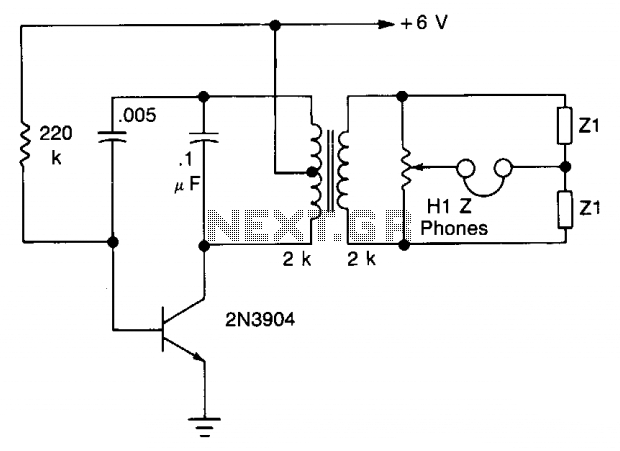
The transistor is configured as an audio oscillator, utilizing an audio transformer in the collector. The secondary winding is connected to a linear potentiometer. The ratio between the two sections of the potentiometer from the slider is proportional to...
Electronics tutorial about active low pass filters, including low pass filter frequency response, op-amp voltage gain, and active filter construction. An active low pass filter (ALPF) is an essential component in electronics, designed to allow low-frequency signals to pass while...
The following circuit illustrates a Robotics IR Navigation Sensor Circuit Diagram. Features include one chip, the 74HC04, and the IR sensor is designed to operate in direct sunlight. The Robotics IR Navigation Sensor Circuit utilizes an inverter IC, specifically the...
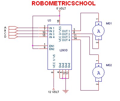
The electronic schematic of a DC motor driver using the L293D, as illustrated in Figure 2, enables the control of two DC motors continuously. It allows for one motor to rotate clockwise while the other rotates counterclockwise. Additionally, all...
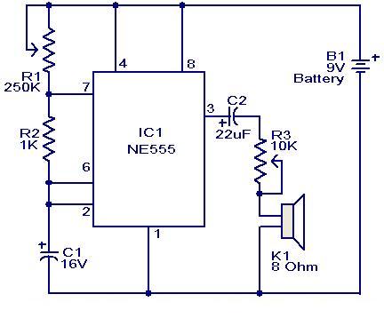
This weblog focuses on electronic circuit schematics, PCB design, DIY kits, and diagrams for electronic projects. A simple circuit utilizing the NE555 IC is presented, which can be employed to generate metronomes. This circuit is particularly beneficial for music...