
hv generator circuit

To modify the transformer, the old primary winding must be removed carefully to avoid damaging the high voltage secondary. If the transformer has all windings encased in plastic, an alternative transformer should be used. The primary winding should consist of 5 turns of 18 AWG wire, with a center tap created by twisting a loop, followed by another 5 turns. This configuration is designated as winding C-D. Additionally, 2 turns of 22 AWG wire should be wound with a loop twisted for a center tap, followed by 2 more turns, which will be referred to as winding A-B.
Transistors Q1 and Q2 will generate significant heat and should be mounted on a large heatsink. After the circuit operates for a minute or two, the transistors should remain cool enough to touch without burning. Resistors R1 and R2 will also heat up during operation. If arcing occurs on the exposed transformer leads, it is recommended to lower the voltage for T1. When using a power supply, the voltage should be adjusted downward as needed.
The first image illustrates the high voltage generator without a voltage multiplier, showcasing the intensity of the arc. The second image depicts the generator with a voltage multiplier, highlighting the increased brightness of the arc. Safety precautions are critical when operating this circuit; it is advised to stand on an insulated surface, such as a pie plate on a plastic bucket, connected to the high voltage generator, which may be charged to around 40,000V. It is essential to have an assistant manage the power supply and avoid touching any conductive materials when charged. Personal items such as watches should be removed prior to operation.
This circuit can serve as an educational tool to illustrate principles of high voltage and high frequency, as well as practical applications in electronics. Proper construction and safety measures are paramount to ensure safe operation and effective demonstration of the circuit's capabilities.This is a fun and useful circuit for demonstrating high frequency high voltge. It can produce up to about 30KV, depending on the transformer used. It is cheap and easy to make, thanks to the standard TV flyback transformer used. It can power LASERS (although I have never tried), demonstrate St. Elmo`s fire, and even cause a fluorescent bulb to ligh t from as much as 2 feet away. T2 is a high voltage flyback transformer salvaged from an old TV, or ordered from Fair Radio Sales (see Where To Get Parts ). Look for the biggest, most intimidating transformer you can find. Old tube TV`s are a good place to look. The transformer should not have a rectifier built in. You will need to rewind the transformer`s primary. First, remove the old primary, being careful not to damage the high voltage secondary. If the transformer is wound with all windings incased in plastic, use another transformer. Second, wind on 5 turns of 18 AWG wire, twist a loop (center tap), and then wind on 5 more turns. This becomes winding C-D. Now, wind on 2 turns of 22 AWG wire, twist a loop, and wind on 2 more turns. This becomes winding A-B. Q1 and Q2 will run HOT if not used with a large heatsink. After the circuit has been running for a minute or two, you should still be able to put your finger on the transistors without being burnt.
Also, R1 and R2 will run hot. If you experience arcing on the exposed transformer leads, select a lower voltage for T1. If you are powering the circuit with a power supply (see Power Supply ), just crank down the voltage. The first picture is the high voltage generator without the voltage multiplier. Notice how hot the arc looks. The second picture is the high voltage generator with a voltage multiplier installed. Notice how much brighter the arc is. The above pictures of myself were taken with me standing on an pie plate that was resting on the top of a plastic bucket.
The pie plate was connected to the high voltage generator and charged to about 40, 000V. If you do this, be sure to have someone else turn on and off the high voltage generator. Also, don`t touch anything when you are charged. Have everything you are going to hold/play with already sitting on the bucket and away from grounded objects. Remember to take off your watch. 🔗 External reference
Related Circuits
Power outages following a call prevent the re-closure of a circuit, which can help avoid the use of electrical appliances after the power grid is restored. If appliances are left on and a call occurs, it may lead to...
The circuit was taken from an old Elektor electronics magazine and is a compact design suitable for generating high-intensity lighting effects during festivals, parties, and gatherings. Diodes D1 and D2, along with capacitors C1 and C2, form a voltage...

This liquid detector circuit diagram is designed using common electronic components. The liquid detector can activate an active buzzer to produce sound when a certain water level is reached. Since the water sensor and control circuit for the buzzer...

In this application, a BA1404 is utilized to generate an FM MPX baseband signal. This signal modulates a crystal oscillator (Q3) through a dual varactor series modulator. This transmitter can be used to play CD audio on an existing...
Temperature indicators and temperature-based products have garnered significant interest due to their numerous applications and various possible solutions, each presenting unique advantages and disadvantages. This concept focuses on a sensor interface that delivers high accuracy while minimizing board space....
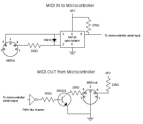
MIDI, or Musical Instrument Digital Interface, is a specification for a communications protocol between digital synthesizers and other digital music devices. It was developed to be as simple and general as possible, providing synthesizer manufacturers with significant flexibility while...