
HV SUPPLY METERING & OVERVOLTAGE TRIP
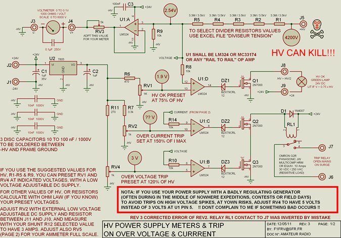
High voltage resistors, such as the SFERNICE or PHILIPS type VR37, are critical components in constructing a high voltage divider. With a voltage rating of 3.5 kV and a power rating of 0.4 W, these resistors facilitate the safe division of high voltage levels for various applications. Their affordability, even when purchased in bulk, makes them a practical choice for hobbyists and professionals alike.
The design of the power command circuit is essential for ensuring operational safety and reliability. It integrates push buttons and an auto-maintain loop, which allows for consistent operation of the mains power relay. The inclusion of a "soft start" feature in the power supply schematic is particularly beneficial as it mitigates inrush currents that can damage components during startup.
For accurate measurement and calibration, meter scales can be developed using available software tools like F5BU's GALVA and WB6BLD's meter software, providing flexibility in design and functionality. Additional resources, such as downloadable files for PCB layout, bills of materials, and datasheets, enhance the ease of assembly and ensure that all necessary components are accounted for.
The power supply is engineered for high-performance applications, capable of supporting amplifiers with power ratings of up to 5 kW, making it suitable for various high-power audio applications. The custom-made transformer, specifically designed for this application, is a vital element that contributes to the overall performance and efficiency of the power supply.
Safety considerations are paramount in high voltage applications. The design incorporates positive safety features that ensure the system will shut down in the event of power interruptions or other faults. The use of special high voltage wiring and heat-shrink tubing for terminal connections further enhances safety, minimizing the risk of electrical failures.
Fuses are selected based on the safety budget, and the importance of maintaining a safety distance of greater than 25 mm between ground and high voltage parts cannot be overstated. The use of screw terminals instead of soldered connections adds an additional layer of reliability to the control and mains parts of the circuit. Overall, this comprehensive approach to design and safety ensures that the high voltage power supply operates effectively and securely in demanding environments.High voltage resistors for HV divider are SFERNICE or PHILIPS type VR37 (3. 5 kV - 0. 4 W). They are NOT expansive (even if they are sold by 25 or 50 units) and it is always useful to have some in junkbox if you want to make high voltage divider for other applications. The power command circuit, on mains supply MUST be fugitive with push buttonsand auto maintain loop
on mains power relay. See schematic (in French) of my power supply with "soft start" circuit. Nota: for start-up, the trip relay contact shall be short circuited by the "ON" push button. Meter scales can be made with F5BU`s FREEWARE GALVA easy to use (french & english), or, with WB6BLD`s (unfortunately NO LONGER FREE) METER available on the net. Download file for PCB with bill of materials, datasheets, EXCEL calculation sheets, layout for high voltage fuses, and this PDF file in: HV METERS & TRIP F1FRV.
ZIP You can also simulate and predict accurately the results of your power supply (no load, under load, ripple. ), in using the excellent freeware PSUD2 available in the links page. See also associated page HV RECTIFIER BRIDGE with PCB, and PCB for "ersatz " of SILEC P800H: 8000V@3Amps controled avalanche rectifier (hard to find now.
). Cette alimentation a G©tG© concue pour alimenter soit un amplificateur de puissance 4 ou 5 kW (2 x GS35 ou 1 x GU-78b), soit deux amplificateurs de la classe 2000/2500 Watts (1 x GS35 ou 1 x 8877) en fonctionnement SIMULTANE. Le transformateur nG©cG©ssaire a G©tG© rG©alisG© sur mesures par une petite sociG©tG© trG¨s compG©tente et trG¨s compG©titive (voir coordonnG©es et prix avec les photos).
Le poids de l`alimentation complG¨te (~110 kg) nG©cG©ssite l`utilisation d`un chassis G©quipG© de solides roulettes. La sG©curitG© est TRES importante. Tous les circuits de commande sont G sG©curitG© POSITIVE. C`est G dire qu`en cas de coupure (mG me fugitive) de l`alimentation secteur, d`ouverture de l`armoire ou de rupture d`un fil, l`ensemble se met G l`arrG t.
Pour la partie HT du montage, n`utiliser que du fil de cablage spG©cial haute tension, et soigner le montage des cosses de raccordement (utiliser de la gaine thermorG©tractable), afin d`G©viter toute rupture en service. Choisir des fusibles "F" ou "FF" suivant l`argent que vous comptez mettre pour la sG©curitG© (rapport 1 G 5 en prix).
Voir courbes des fusibles dans les documents G tG©lG©charger. NE JAMAIS OUBLIER LA DISTANCE DE SECURITE >25 mm ENTRE LA MASSE ET TOUTES LES PARTIES SOUS HAUTE TENSION !. Voir les G©quipements de sG©curitG© nG©cG©ssaires. Pour la partie commande et secteur, des bornes G vis sont plus sG»res que des cables soudG©s sur circuit imprimG© ou sur des petits composants de kG©kG©bouilbouills.
🔗 External reference
Related Circuits
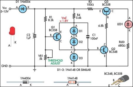
This is a simple low supply rail detection circuit that is inexpensive and can be assembled in approximately 20 minutes. It operates with low power consumption, making it suitable for integration into battery-powered devices. The circuit utilizes three low-cost...
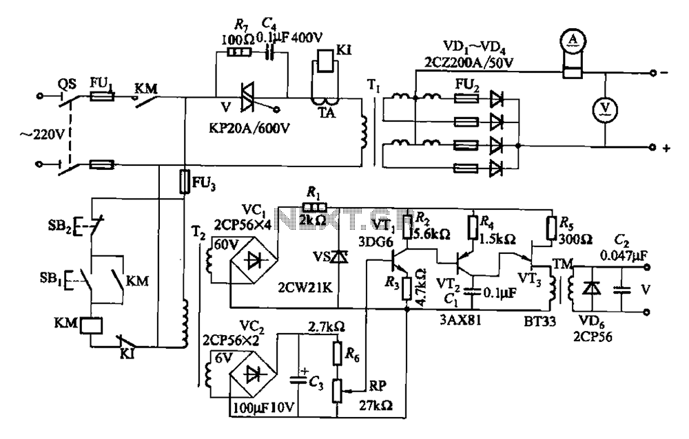
A 500A-6V single-phase power supply circuit designed for thyristor electroplating. This circuit can output a continuous DC current of 500A at 6V, which is adjustable for plating processes. It incorporates a single-junction transistor as part of the trigger circuit,...
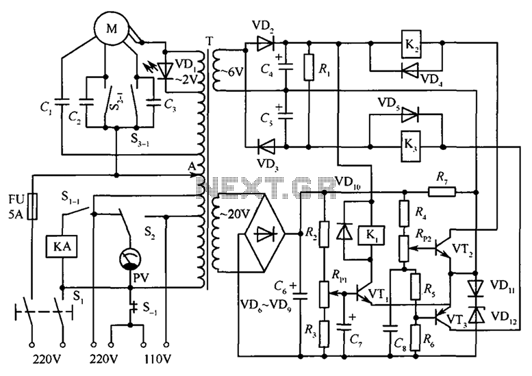
The circuit illustrated in the figure features an automatic voltage regulator (T) that utilizes a servo motor to ensure a constant output voltage. The transistors used are VT1 and VT2 (3DK9C, with a range of 65 to 85) and...
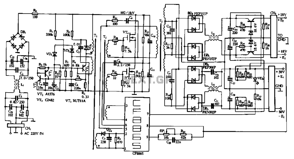
This document describes a specific module utilizing the CF8865 switching power supply circuit, which employs the integrated control module CF8865. In the figure, transistors VT4 and VTs are controlled by the excitation transformer Tz. The output is processed through...
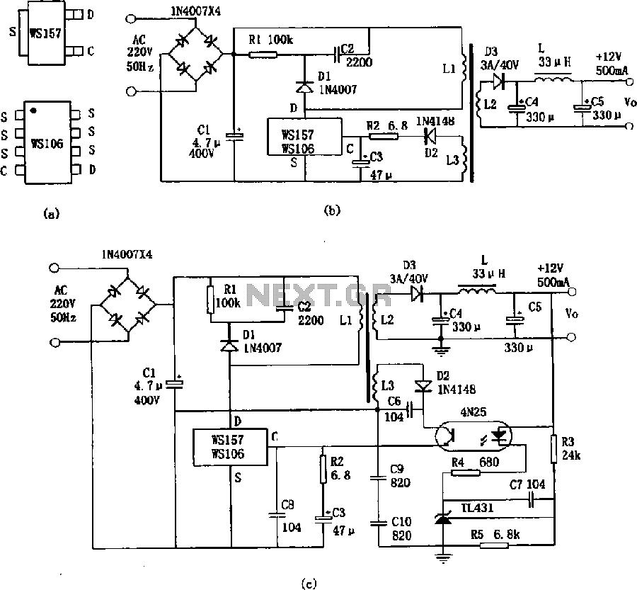
The WS157 or WS106 is a low-power miniature switching power supply that has been developed in recent years. It functions as a regulated switching power supply control device, featuring integrated internal control circuitry and power switches on a single...
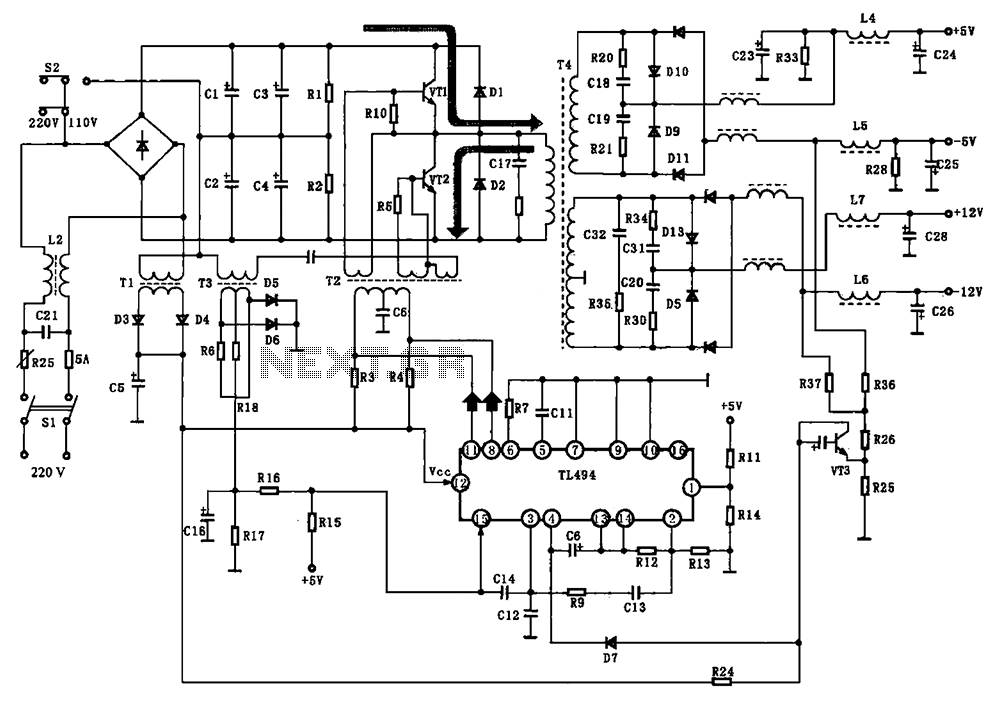
The BE-150 mainframe computer features a switching power supply circuit. The circuit utilizes the oscillation control IC TIA94. A 22V voltage is supplied through the power switch S1, fuse, filter capacitor C21, L2, and a mutual inductance filter, which...