
BE-150 mainframe computer switching power supply circuit
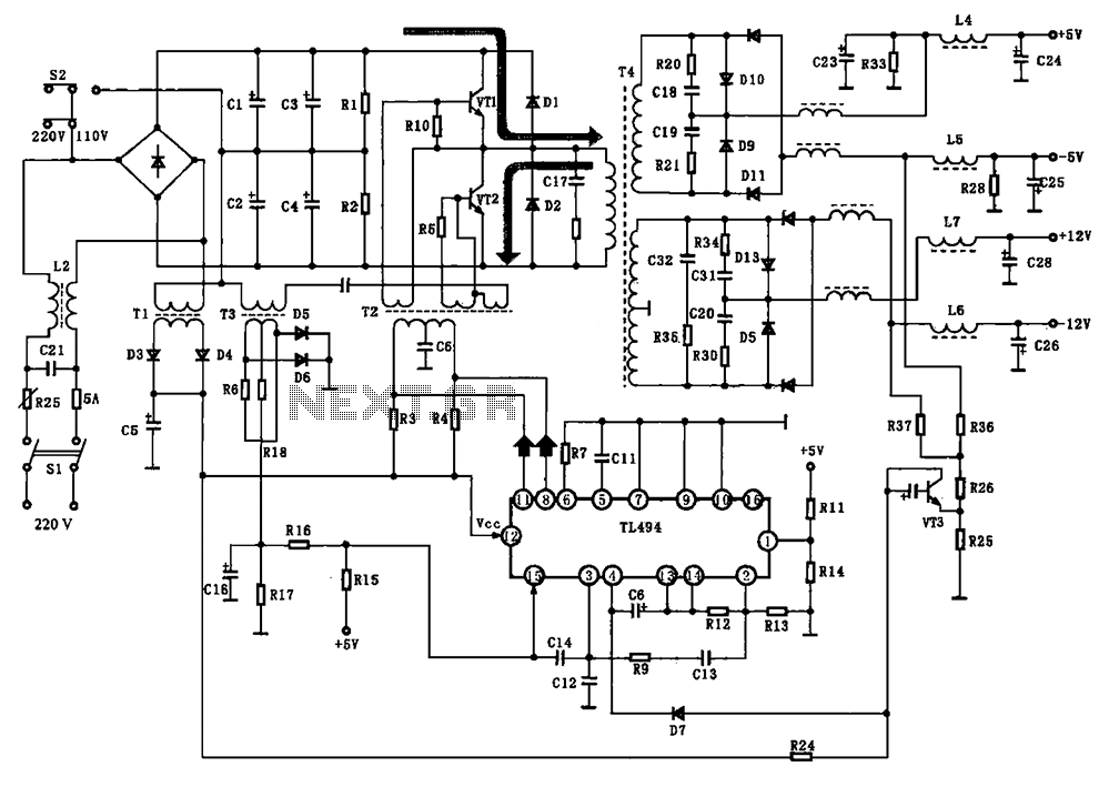
The BE-150 mainframe computer's switching power supply circuit is designed to convert and regulate electrical power efficiently. The circuit begins with a 22V input, which is routed through the power switch S1 and a fuse for protection against overcurrent. Following this, the input passes through a filter capacitor (C21) and an inductor (L2), which together help to smooth out voltage fluctuations and reduce ripple.
The rectification process is performed by a bridge rectifier, transforming the AC voltage into a stable 30V DC output. This voltage is then utilized to power the switching transistors VT1 and VT2. The oscillation control IC TIA94 plays a crucial role in generating the necessary control signals. The output from TIA94 is an oscillation signal that is transmitted to the base of the transistors via transformer T2, which serves as a coupling element.
Transistors VT1 and VT2 amplify the switching pulses, which are then applied to the primary winding of transformer T4. The transformer T4 is vital for voltage transformation and isolation between the primary and secondary circuits. The secondary winding of T4 provides rectified and filtered outputs, yielding multiple DC voltage levels, specifically +5V and +12V, which are essential for powering various components of the mainframe computer.
Additionally, components Tl and I2 are responsible for generating a start signal during the boot process, ensuring that the circuit initializes correctly. The operation of T2 is essential for maintaining the oscillator signal, enabling continuous operation of the power supply circuit. This design allows for a reliable and efficient power management solution tailored for the BE-150 mainframe computer, ensuring stable operation under varying load conditions. BE-150 mainframe computer switching power supply circuit The host computer is shown in BE-150-type switching power supply circuit, the oscillation control IC to switch TIA94. A C 22V voltage through the power supply switch S1, fuse, filter capacitor C21, L2 and mutual inductance filter rectifier bridge rectifier heap to 30V DC for the switch VT1, VT2 provide voltage. IC TIA94, foot switch output oscillation signal, the transformer T2 for the switch VT1, VI2 base providing a driving pulse, switching pulse by VT1, VT2 after amplification applied to the transformer primary T4, T4 of the secondary rectified, filtered multiple sets of output DC voltage +5 V, + 12 V.
Tl, I2 formation start signal at boot time, the pros and cons of T2 after work provided to maintain the oscillator signal fed windings.
Related Circuits
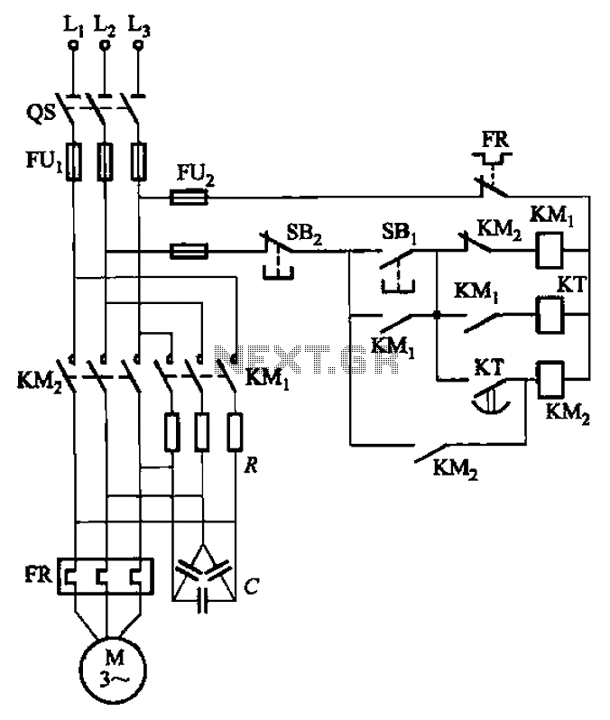
The circuit depicted in Figure 3-35 demonstrates a method for starting a motor that transitions to full voltage through a step-down switching process. This approach provides an uninterruptible power supply, effectively preventing issues related to switching currents that may...
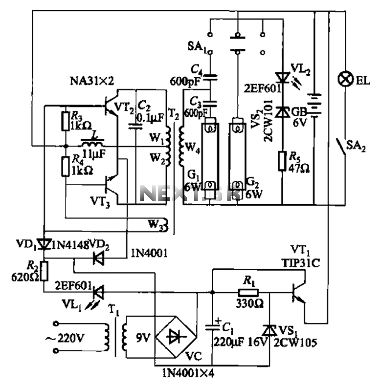
This is a Nissan Panasonic rechargeable emergency fluorescent lamp circuit. It features built-in 6V, 4Ah high-energy batteries that can be directly charged. The circuit supports two 6W fluorescent lamps. It includes functional switches SAi and SAz. When SAi is...
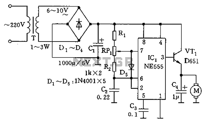
The circuit utilizes a 555 timer as the core component to create an astable multivibrator. The oscillation period T is given by the formula T = 0.693 (R1 + 2R2) C1, which corresponds to an oscillation frequency of approximately...
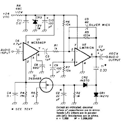
An audio signal applied to VI is passed through the operational amplifier 741, U2. After being amplified, the output signal V2 is sampled and applied to a negative voltage doubler/rectifier circuit composed of diodes CR1 and CR2, along with...
Children often go missing, causing immense suffering and economic losses for families. This situation also presents opportunities for unscrupulous child traffickers to exploit. To address this issue, a radio alarm system has been designed, which consists of a transmitter...
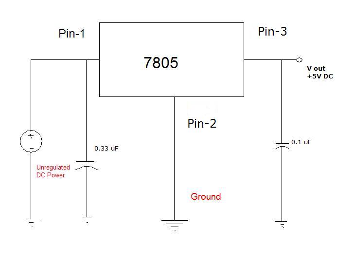
Many different devices require DC power and thus need an I.T.E power supply. I.T.E stands for "Information Technology Equipment." An example of such a device is an iPod speaker system that is no longer functional, which originally came with...
Warning: include(partials/cookie-banner.php): Failed to open stream: Permission denied in /var/www/html/nextgr/view-circuit.php on line 713
Warning: include(): Failed opening 'partials/cookie-banner.php' for inclusion (include_path='.:/usr/share/php') in /var/www/html/nextgr/view-circuit.php on line 713