
Low Supply Rail Detection
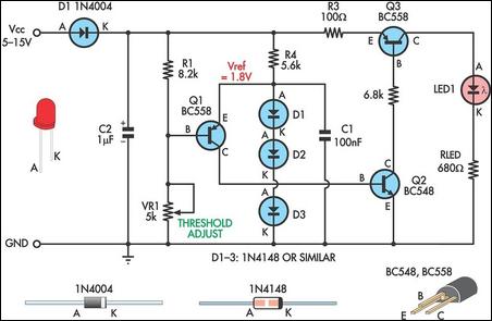
The low supply rail detection circuit is designed to provide a visual indication of supply voltage levels using a simple transistor-based architecture. The circuit's core components include three transistors (Q1, Q2, and Q3), which form a cascade that amplifies the detection of low voltage conditions. The use of diodes D1-D3 to establish a 1.8V reference voltage is critical for ensuring reliable operation, as it sets the threshold for activation of Q1.
The voltage divider created by resistors R1 and VR1 is essential for monitoring the supply voltage. As the input voltage drops, the voltage across the divider also decreases. When this voltage falls below the 1.8V reference, Q1 turns on, allowing current to flow through Q2 and subsequently activating Q3. The output of Q3 is connected to LED1, which serves as the visual indicator. The relationship between the bias current flowing through Q2 and the brightness of LED1 provides a clear, proportional representation of the supply voltage's severity.
The adjustment of trimpot VR1 allows for fine-tuning of the threshold at which LED1 activates, making the circuit versatile for different applications and desired low-voltage levels. The low current consumption of less than 2mA when the LED is off ensures that the circuit is energy-efficient, a crucial characteristic for battery-operated devices.
For applications requiring different operating voltages, the resistor RLED can be calculated to maintain optimal LED performance. This adaptability makes the circuit suitable for a variety of voltage ranges, ensuring its functionality across multiple devices. Overall, this low supply rail detection circuit provides an effective and economical solution for monitoring voltage levels in battery-powered applications.Here`s a simple low supply rail detection circuit that costs peanuts and takes just 20 minutes or so to make. Its power consumption is quite low, so it could easily be built into battery-powered devices. Instead of using an op amp, the circuit is built around three low-cost transistors (Q1-Q3). Diodes D1-D3 form a 1. 8V voltage reference (Vref) for the emitter of Q1. If the voltage across the voltage divider formed by R1 and VR1 is less than this, Q1 turns on and supplies Q2 with base bias current. This turns on Q3 in proportion to this bias current which then drives LED1. The brightness of the LED gives an indication of the severity of the low voltage condition. The brighter the LED, the lower the supply voltage. Trimpot VR1 is adjusted so that LED1 just comes on at the desired low-voltage point. The current consumption is typically less than 2mA when LED1 is off. Finally, the value shown for RLED is suitable for 6-12V operation. For other voltages, RLED can be calculated using the formula RLED = (Vcc 1. 8)/0. 01 (this equates to a current of about 10mA). 🔗 External reference
Related Circuits
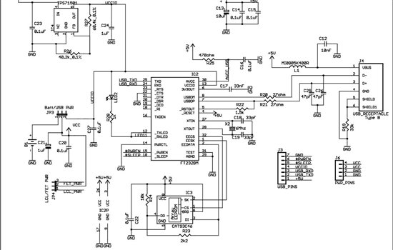
As found in SLAA458, the revised pulse oximeter application, an image of the USB schematic is attached, which is used to output collected data. There are a few questions regarding this schematic: 1) What do J3 and J6 correspond...
This circuit illustrates the power supply wiring diagram for the Nissan 300ZX, a sports car known as the Fairlady Z. Components include the lighting switch, ECCS, and fuse. The power supply wiring diagram for the Nissan 300ZX is essential for...
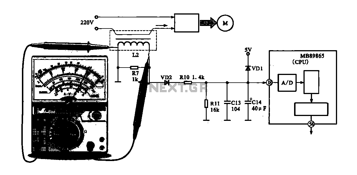
A current-voltage conversion circuit is commonly utilized in current detection applications. An example is the current detection circuit for a ring inverter air conditioner, which primarily serves to monitor the supply current of the compressor motor. Excessive current can...
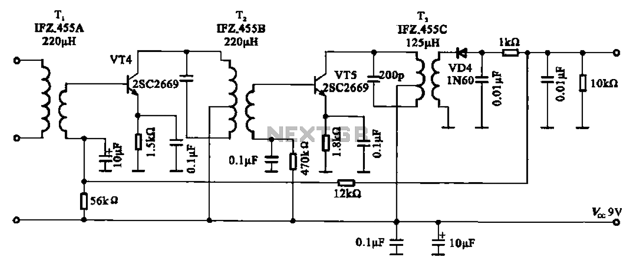
AM radio shows the IF amplifier and detector circuit. The mixer receives the intermediate frequency output signal from the transformer after the device. This signal is applied to the base of the intermediate frequency transistor VT4. The collector load...
The following circuit diagram depicts a variable power supply controlled by a PIC microcontroller. An LCD display is utilized to show the actual output current and voltage values. This digital power supply incorporates a push-button switch to adjust the...
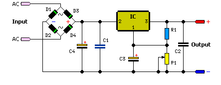
The simple method to power your projects is illustrated in the circuit diagram of a regulated power supply. This compact power supply delivers a stable voltage. This regulated power supply circuit is designed to convert an unregulated input voltage into...